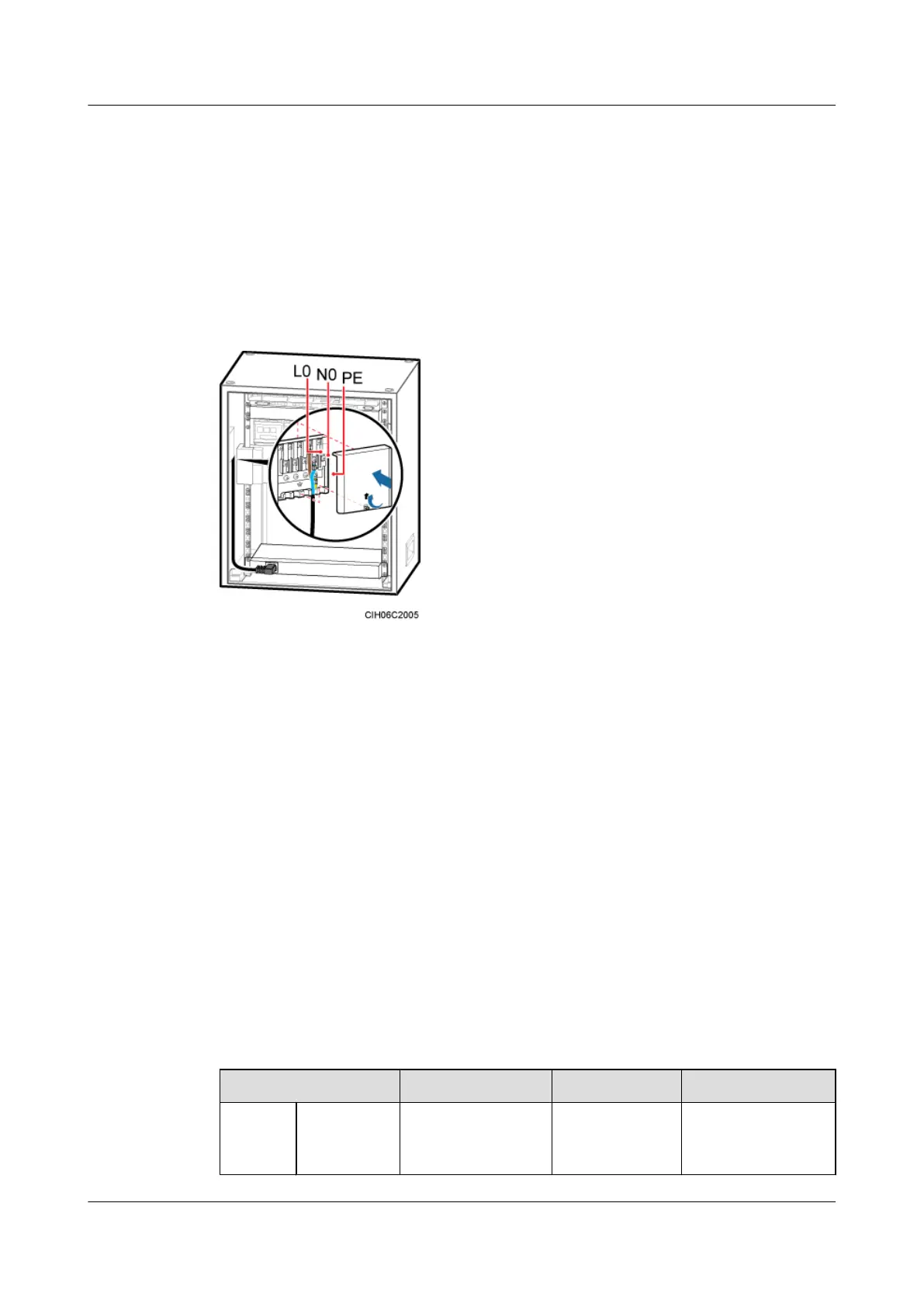
Step 2 Install a power cable for the heater, as shown in Figure 6-54.
1. Remove the cover plate from the junction box.
2. Respectively connect the OT terminals on the brown, blue, and yellow and green wires at
one end of the power cable for the heater to the L0, N0, and PE wiring terminals in the
junction box.
3. Link the C13 connector at the other end to the power supply socket on the heater.
Figure 6-54 Installing a power cable for the AC heater
Step 3 Route and bind the cables. For details, see 6.5.1 Cabling Requirements.
Step 4 Label the installed cables. For details, see Attaching a Cable-Tying Label.
----End
6.4.6 (Optional) Installing an EMUA
This section describes the procedures for installing an EMUA and related cables in an APM30H.
An EMUA can be installed in a reserved 1 U space in the APM30H based on actual requirements.
Prerequisite
The tools such as the screwdriver and ESD gloves are available.
Context
Table 6-4 describes the cables related to the EMUA.
Table 6-4 Cables related to the EMUA
Cable List
One End The Other End Remarks
Power
cable for
RTN(+)
cable
Easy power
receptacle (pressfit
type) connector
Cord end
terminal
Black
DBS3900 (Ver.B)
Installation Guide
6 Outdoor Scenario with AC Power Supply (BBU Installed
in an APM30H)
Issue 06 (2011-09-15) Huawei Proprietary and Confidential
Copyright © Huawei Technologies Co., Ltd.
61
 Loading...