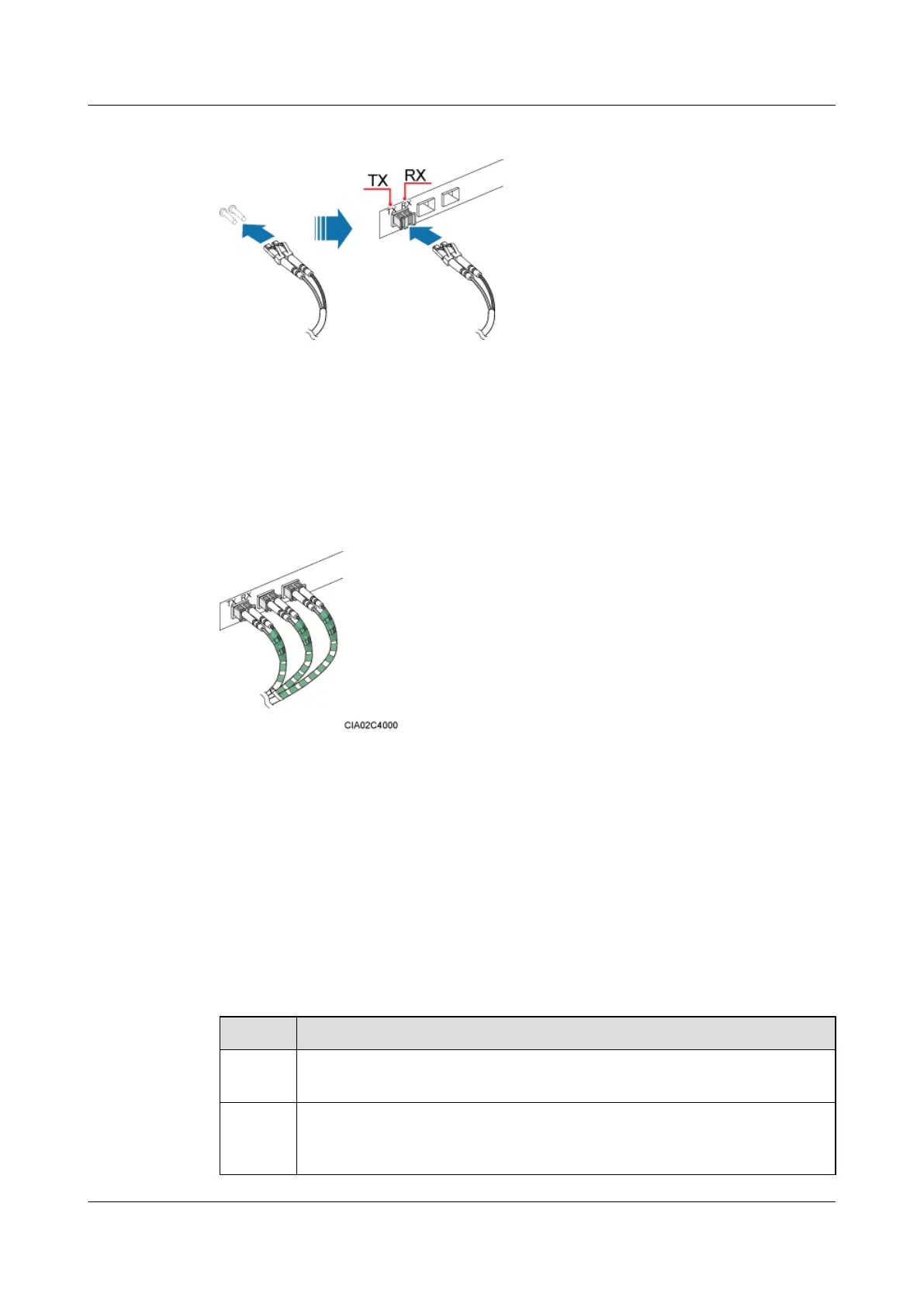
Figure 7-84 Installing a CPRI optical cable
Step 3 Route the CPRI optical cable along the left of the cabinet, and then lead it out of the cabinet
from the cable hole on the left of the bottom. For details, see 7.5.1 Cabling Requirements.
Step 4 Attach labels on the optical cable. For details, see Attaching a Sign Plate Label.
Step 5 Coil the optical fiber with winding plastic tape at the end connected to the BBU. The tape is
coiled between the optical connector and the first cable tie on the cabinet, as shown in Figure
7-85.
Figure 7-85 Coiling the optical fiber with winding plastic tape
----End
7.6 Installation Checklist
Check the installation items, installation environment, and cable-related items after the cabinets
and devices are all installed.
Cabinet Installation Checklist
Table 7-8 describes the cabinet installation checklist.
Table 7-8 Cabinet installation checklist
No.
Item
1 The installation position of the cabinet strictly complies with the engineering
design.
2 In the wall-mounted scenario, the holes of the mounting ears are well aligned with
the holes of the expansion bolt assemblies. In addition, the mounting ears are
secured on the wall evenly and steadily.
DBS3900 (Ver.B)
Installation Guide
7 Outdoor Scenario with DC Power Supply (BBU Installed
in a TMC11H)
Issue 06 (2011-09-15) Huawei Proprietary and Confidential
Copyright © Huawei Technologies Co., Ltd.
209
 Loading...