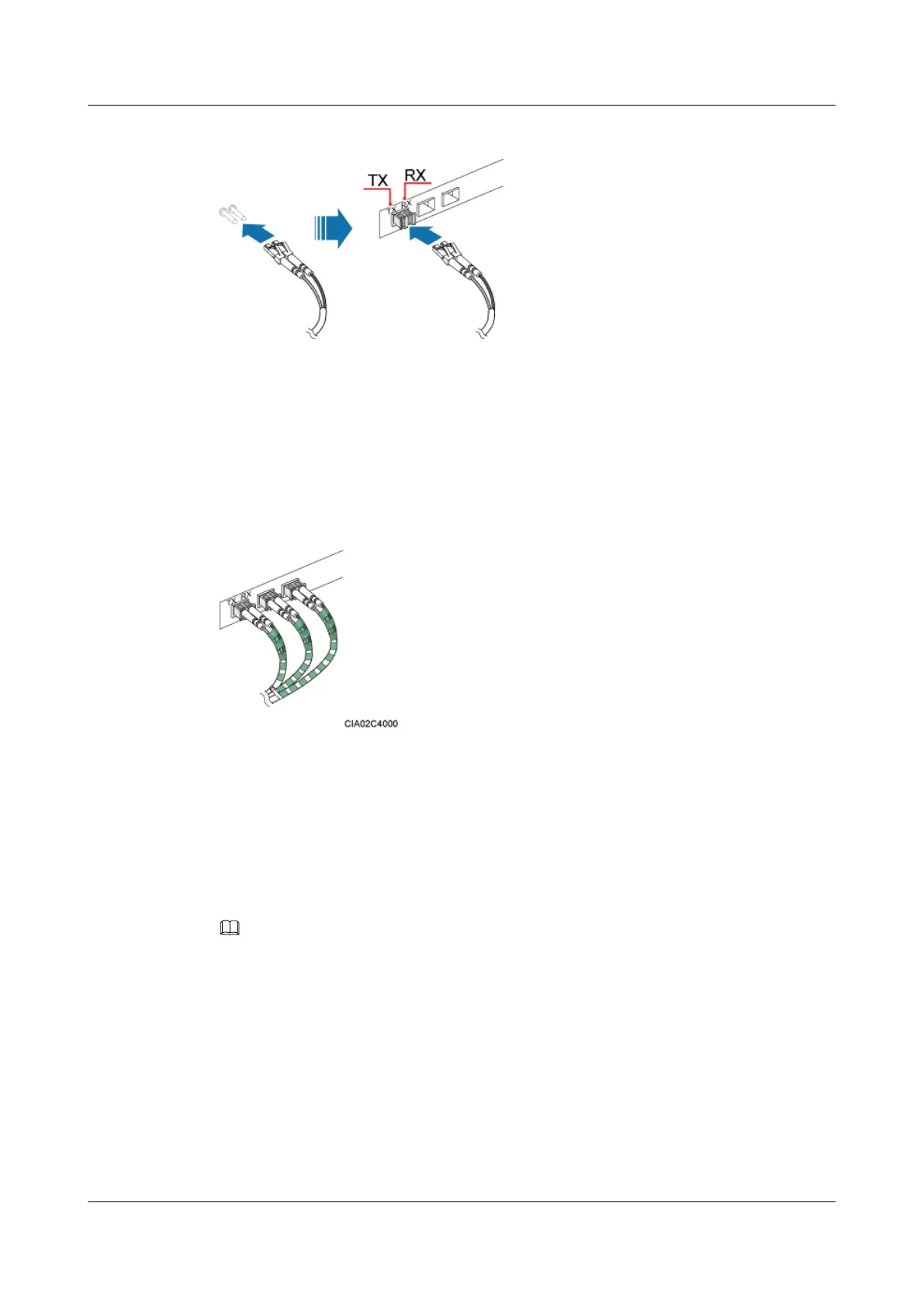
Figure 9-31 Installing a CPRI optical cable
Step 3 Route the CPRI optical cable along the left of the cabinet, and then lead it out of the cabinet
from the cable hole on the left of the bottom. For details, see 9.4.1 Cabling Requirements.
Step 4 Attach labels on the optical cable. For details, see Attaching a Sign Plate Label.
Step 5 Coil the optical fiber with winding plastic tape at the end connected to the BBU. The tape is
coiled between the optical connector and the first cable tie on the cabinet, as shown in Figure
9-32.
Figure 9-32 Coiling the optical fiber with winding plastic tape
----End
9.4.8 Installing a GPS Clock Signal Cable
The GPS clock signal cable is an optional cable that transmits GPS clock signals from the GPS
antenna system to the BBU. The GPS clock signals serve as the clock reference of the BBU.
Context
NOTE
Only a dual-satellite receiver needs to be installed onsite.
Procedure
Step 1 Remove the two M3 screws on the panel, and then pull out the USCU, as shown in Figure
9-33.
DBS3900 (Ver.B)
Installation Guide
9 Outdoor Scenario with DC Power Supply (BBU Installed
in an OMB)
Issue 06 (2011-09-15) Huawei Proprietary and Confidential
Copyright © Huawei Technologies Co., Ltd.
318
 Loading...