Figure 8-35 Installing the OT terminal in the correct manner
2. Install an equipotential cable in each cabinet, as shown in Figure 8-36.
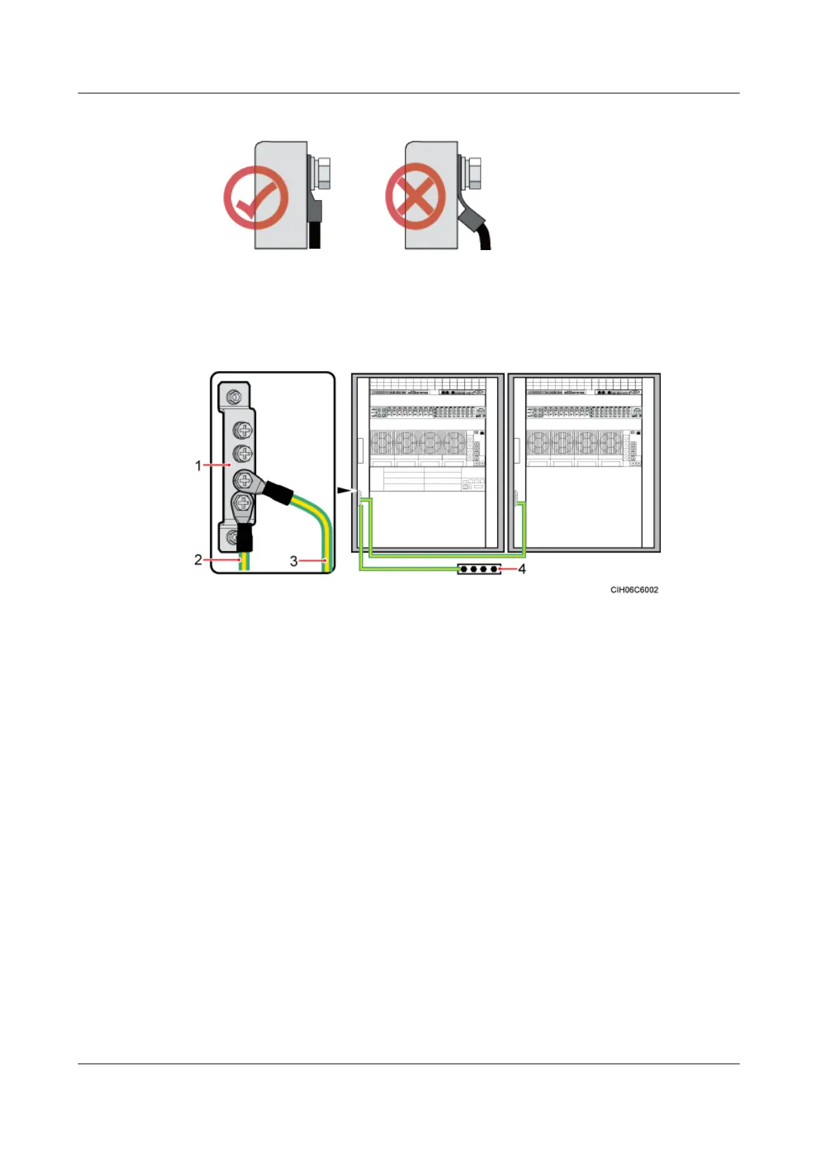
Figure 8-36 Installing a PGND cable and equipotential cable
(1) Ground bar on the inner side of the cabinet
(2) PGND cable (3) Equipotential cable (4) Ground busbar
Step 3 Route and bind the cables. For details, see 8.5.1 Cabling Requirements.
Step 4 Label the installed cables. For details, see Attaching a Cable-Tying Label.
Step 5 Run each cable that leaves the cabinet in a PVC corrugated pipe, and then tie the pipe to the
cable hole on the cabinet.
----End
8.4 Installing Components
The BBU and SLPU must be installed in the APM30H. The SOU, EMUA or GPS surge protector
optional based on actual requirements.
8.4.1 Installing a BBU
This section describes the procedure and precautions to be taken for installing a BBU in an
APM30H, TMC11H, or 19-inch rack. A BBU occupies a space of 19 inch wide and 2 U high.
Context
In the triple mode scenario, two BBUs are required. A second BBU is installed in the same
manner as the first BBU.
DBS3900 (Ver.B)
Installation Guide
8 Outdoor Scenario with DC Power Supply (BBU Installed
in a +24 V DC APM30H)
Issue 06 (2011-09-15) Huawei Proprietary and Confidential
Copyright © Huawei Technologies Co., Ltd.
244
 Loading...