Figure 6-35 Installing the OT terminal in the correct manner
2. Install an equi-potential cable in each cabinet, as shown in Figure 6-36.
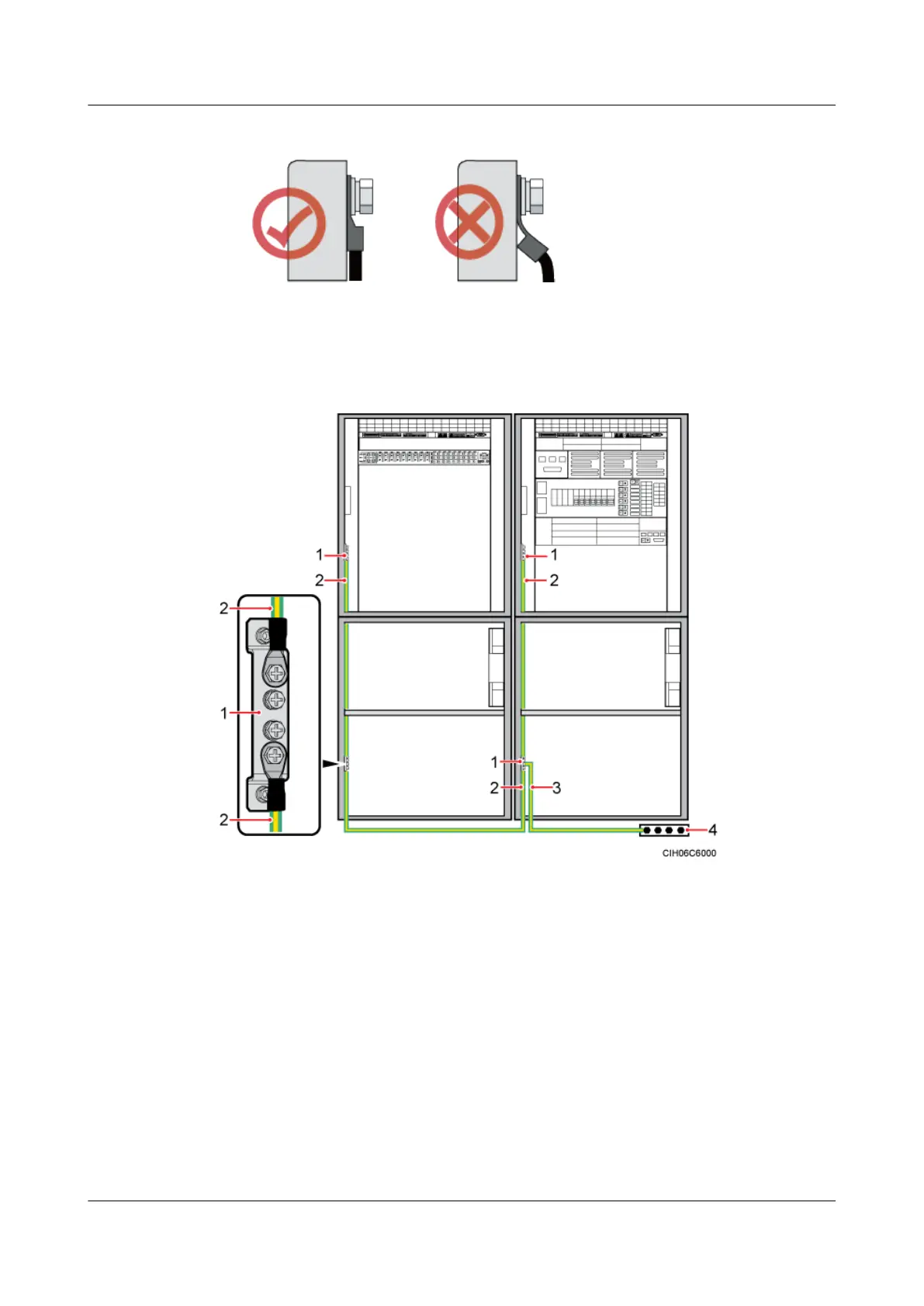
Figure 6-36 Installing a PGND cable and equi-potential cable
(1) Ground bar on the inner side of the cabinet
(2) Equi-potential cable (3) PGND cable (4) Ground busbar
Step 3 Route and bind the cables. For details, see 6.5.1 Cabling Requirements.
Step 4 Label the installed cables. For details, see Attaching a Cable-Tying Label.
Step 5 Run each cable that leaves the cabinet in a PVC corrugated pipe, and then tie the pipe to the
cable hole on the cabinet.
----End
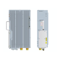
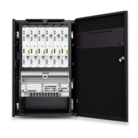
6.4 Installing Components
The BBU and SLPU must be installed in the APM30H and TMC11H. The SOU, heater, EMUA
or GPS surge protector optional based on actual requirements.
DBS3900 (Ver.B)
Installation Guide
6 Outdoor Scenario with AC Power Supply (BBU Installed
in an APM30H)
Issue 06 (2011-09-15) Huawei Proprietary and Confidential
Copyright © Huawei Technologies Co., Ltd.
51
 Loading...