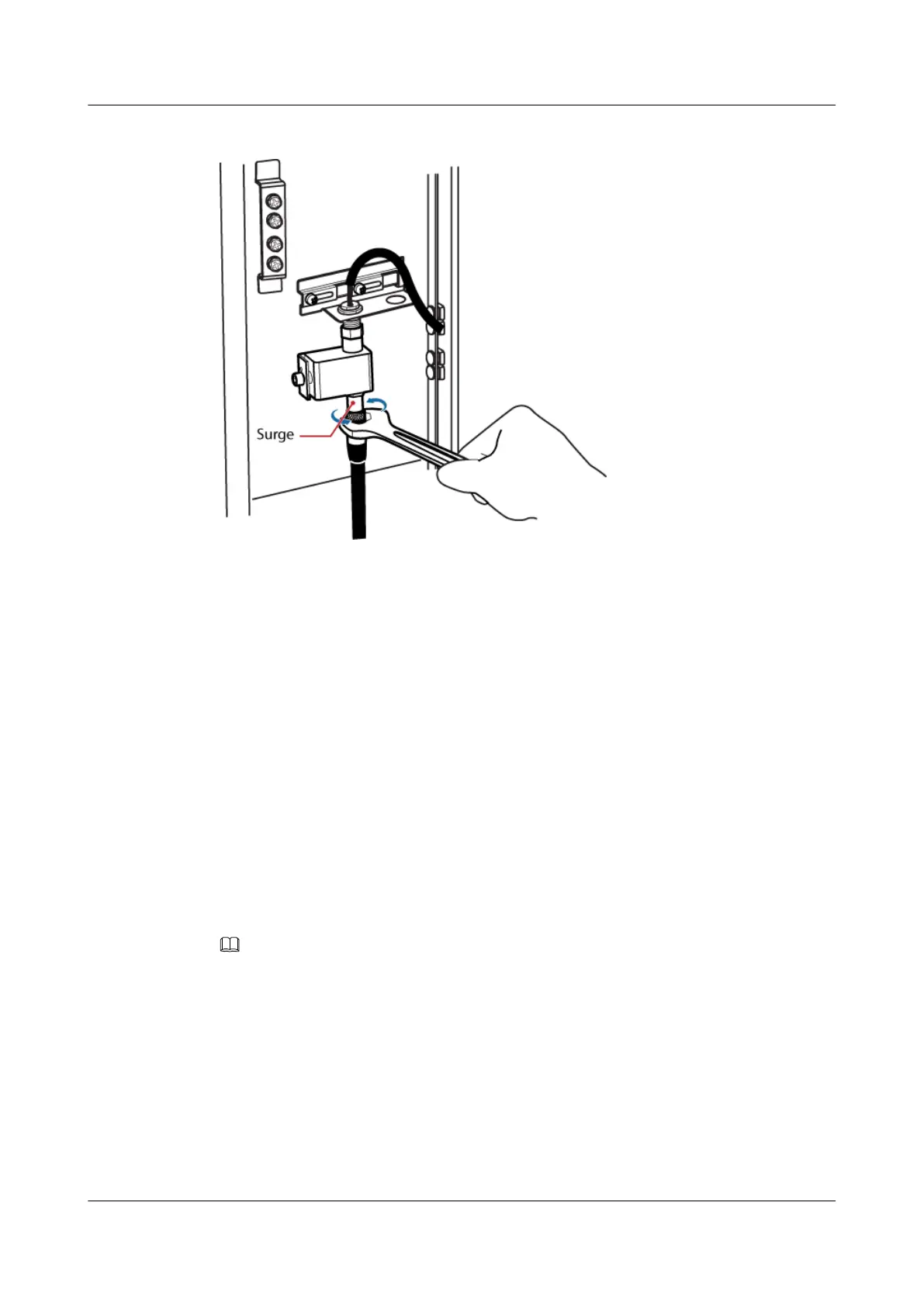
Figure 7-62 Installing the GPS jumper
Step 9 Route the cable by referring to 7.5.1 Cabling Requirements.
Step 10 Attach labels to the installed cable. For details, see Attaching a Sign Plate Label.
----End
7.5 Installing Cables
This section describes the procedures and precautions to be taken for installing power cables,
transmission cables, monitoring signal cables, and CPRI cables when a DBS3900 is deployed
outdoors with DC power supply and the BBU is installed in a TMC11H.
7.5.1 Cabling Requirements
Cables must be routed according to the specified cabling requirements to prevent signal
interference.
NOTE
If a cable listed below is not required, skip the routing requirements of the cable.
General Cabling Requirements
The bending radius of the cables must meet the following specifications:
l The bending radius of the 7/8'' feeder must be more than 250 mm (9.84 in.), and the bending
radius of the 5/4'' feeder must be more than 380 mm (14.96 in.).
l The bending radius of the 1/4'' jumper must be more than 35 mm (1.38 in.). The bending
radius of the super-flexible 1/2'' jumper must be more than 50 mm (1.97 in.), and the bending
radius of the ordinary 1/2'' jumper must be more than 127 mm (5 in.).
DBS3900 (Ver.B)
Installation Guide
7 Outdoor Scenario with DC Power Supply (BBU Installed
in a TMC11H)
Issue 06 (2011-09-15) Huawei Proprietary and Confidential
Copyright © Huawei Technologies Co., Ltd.
188
 Loading...