EasyManua.ls Logo

Huawei DBS3900 User Manual

Huawei DBS3900
556 pages
To Next Page IconTo Next Page
To Previous Page IconTo Previous Page
Page #478 background image
Figure 13-41 Installing the PGND cable
(1) OT terminal (M4)
----End
13.5 Installing IMB03 Cables
This section describes cable connections and the process of installing cables.
NOTE
In the DC power supply scenario, a BBU power cable must be connected to each UPEU if two UPEUs are
installed in the BBU. The 3V3 power connector at one end of each BBU power cable is connected to the
–48V port on each UPEU in the BBU, and the easy power receptacle (pressfit type) connectors at the other
end are connected to the LOAD6 and LOAD7 ports on the DCDU-03B, respectively.
13.5.1 Cabling Requirements
Cables must be routed according to the specified cabling requirements to prevent signal
interference.
NOTE
If a cable listed below is not required, skip the routing requirements of the cable.
General Cabling Requirements
The bending radius of the cables must meet the following specifications:
l The bending radius of the 7/8'' feeder must be more than 250 mm (9.84 in.), and the bending
radius of the 5/4'' feeder must be more than 380 mm (14.96 in.).
l The bending radius of the 1/4'' jumper must be more than 35 mm (1.38 in.). The bending
radius of the super-flexible 1/2'' jumper must be more than 50 mm (1.97 in.), and the bending
radius of the ordinary 1/2'' jumper must be more than 127 mm (5 in.).
DBS3900 (Ver.B)
Installation Guide 13 Indoor Scenario (BBU Installed in an IMB03)
Issue 06 (2011-09-15) Huawei Proprietary and Confidential
Copyright © Huawei Technologies Co., Ltd.
465

Table of Contents

Other manuals for Huawei DBS3900

Question and Answer IconNeed help?

Do you have a question about the Huawei DBS3900 and is the answer not in the manual?

Huawei DBS3900 Specifications

General IconGeneral
BrandHuawei
ModelDBS3900
CategoryAccessories
LanguageEnglish

Summary

1 Changes in the DBS3900 (Ver.B) Installation Guide

2 Installation Preparations

2.1 Document Preparation

Lists the necessary documents to obtain before starting the installation process.

2.2 Tools and Instruments

Lists all the required tools and instruments that must be prepared before installation.

2.3 Skills and Requirements for Onsite Personnel

Outlines the necessary qualifications, training, and safety knowledge for installation personnel.

3 Installation Scenarios

4 Unpacking the Equipment

5 Obtaining the ESN

6 Outdoor Scenario with AC Power Supply (BBU Installed in an APM30H)

6.1 Installation Process

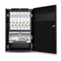
Outlines the overall process for installing the BBU in an APM30H for outdoor AC power scenarios.

6.2 Installing a Cabinet

Details cabinet installation on concrete floors, metal poles, or walls.

6.3 Installing a PGND Cable and Equi-potential Cable

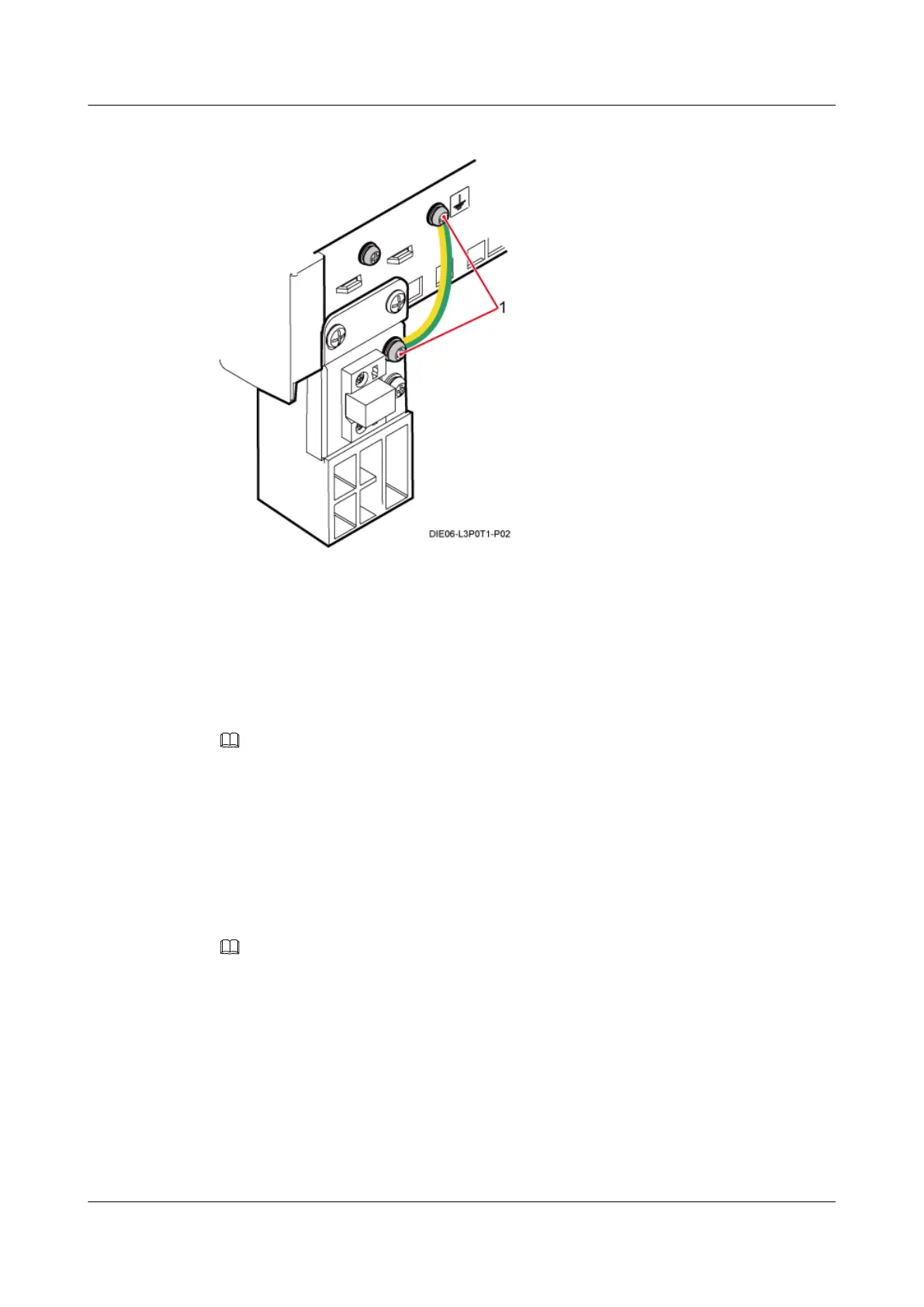
Explains how to connect the PGND and equipotential cables for proper grounding.

6.4 Installing Components

Describes the installation procedures for key components like BBU and SLPU.

6.5 Installing Cables

Covers the installation procedures for various cable types.

6.6 Installing the Batteries and Related Cables

Provides procedures for installing batteries and their associated cabling.

6.7 Installation Checklist

Offers a comprehensive checklist to verify the completion of the cabinet installation.

6.8 Power-On Check

Details the steps for checking the system power-on status.

Related product manuals