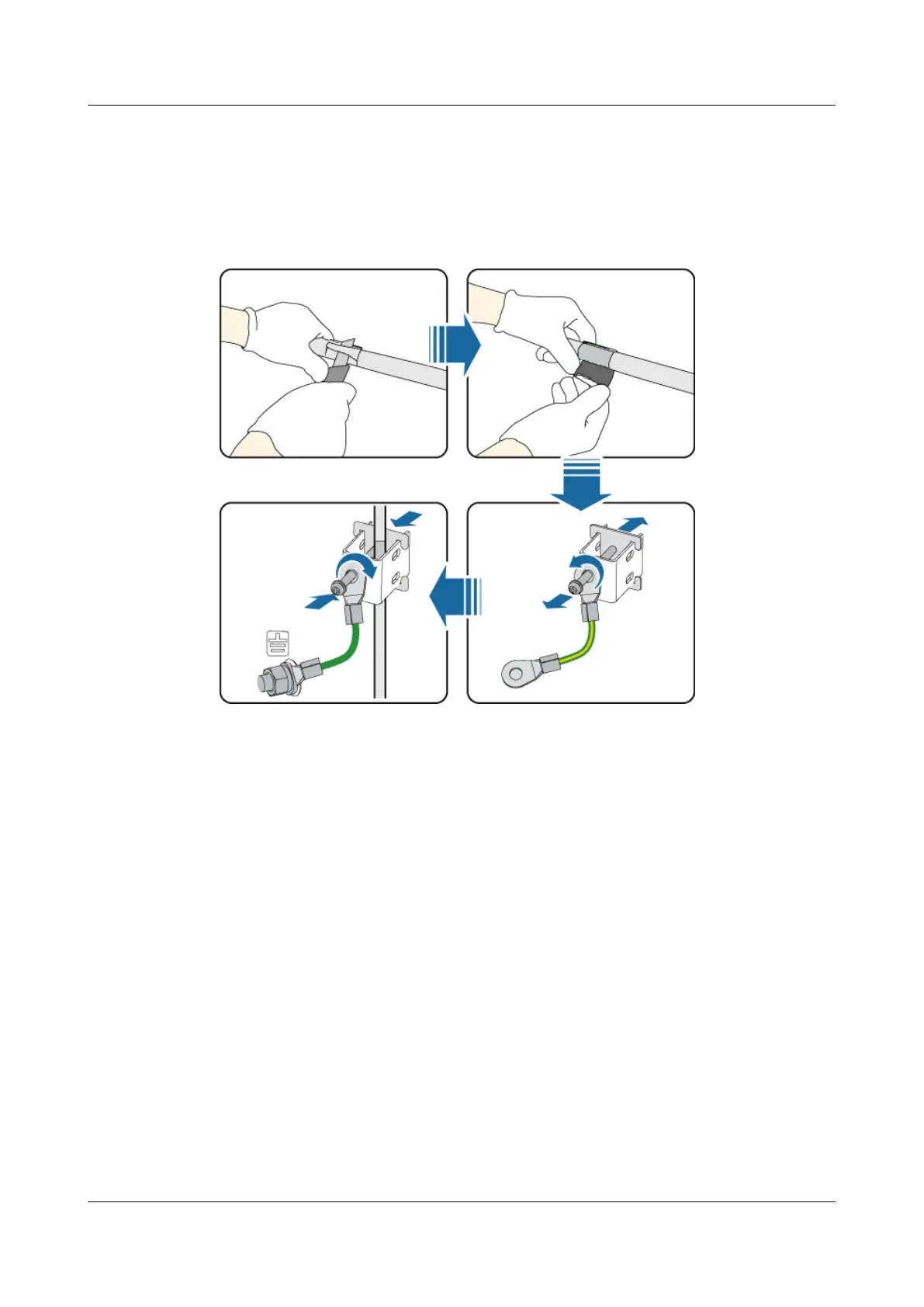
Step 3 In a position 20 cm away from the cable outlet module, strip the jacket for about 25 mm off the
RRU power cable to expose the shield layer. Thread the cable through the ground clip to ensure
full contact between the shield layer and the ground clip, and then tighten the M4 screws on the
clip until the tightening torque reaches 1.2 N·m, as shown in Figure 14-42.
Figure 14-42 Installing a grounding clip
Step 4 Route the cable by referring to 13.5.1 Cabling Requirements, and then use cable ties to bind
the cable.
Step 5 Label the installed cables by referring to Attaching a Sign Plate Label.
----End
14.5.4 Installing a Monitoring Signal Cable for the RRU
A monitoring signal cable for the RRU connects an RRU to the APM30H, enabling the
monitoring of the RRU.
Procedure
Step 1 Install a monitoring signal cable for the RRU, as shown in Figure 14-43.
1. Connect one end of the monitoring signal cable for the RRU to the EXT_ALM port on the
RRU.
2. Connect the other end to the IN0 and IN1 ports on the USLP2 in the SLPU in the APM30H.
DBS3900 (Ver.B)
Installation Guide
14 Indoor Scenario with DC Power Supply (BBU Installed
Indoors and RRU Powered Outdoors)
Issue 06 (2011-09-15) Huawei Proprietary and Confidential
Copyright © Huawei Technologies Co., Ltd.
533
 Loading...