Step 4 Attach labels on the optical cable. For details, see Attaching a Sign Plate Label.
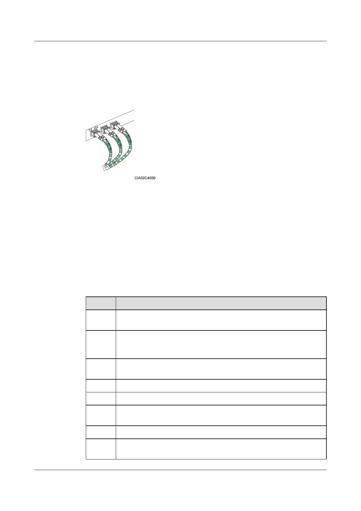
Step 5 Coil the optical fiber with winding plastic tape at the end connected to the BBU. The tape is
coiled between the optical connector and the first cable tie on the cabinet, as shown in Figure
12-24.
Figure 12-24 Coiling the optical fiber with winding plastic tape
----End
12.5 Installation Checklist
Check the installation items, installation environment, and cable-related items after the cabinets
and devices are all installed.
Cabinet Installation Checklist
Table 12-6 describes the cabinet installation checklist.
Table 12-6 Cabinet installation checklist
No.
Item
1 The installation position of the cabinet strictly complies with the engineering
design.
2 In the wall-mounted scenario, the holes of the mounting ears are well aligned with
the holes of the expansion bolt assemblies. In addition, the mounting ears are
secured on the wall evenly and steadily.
3 In the metal-pole-mounted scenario, the supports for the metal pole are secure on
the floor.
4 If the cabinet is installed on the floor, the base is securely installed.
5 Either the horizontal error or vertical error of the cabinet is less than 3 mm.
6 All the bolts, especially those for electrical connections, are tight. Both the spring
washer and the flat washer are installed in the correct sequence.
7 The cabinet is neat and clean.
8 The paint on the surface is intact. If any paint is damaged, you must apply touch-
up paint to avoid erosion.
DBS3900 (Ver.B)
Installation Guide
12 Indoor Scenario with DC Power Supply (BBU Installed in
a 19-Inch Rack)
Issue 06 (2011-09-15) Huawei Proprietary and Confidential
Copyright © Huawei Technologies Co., Ltd.
427
 Loading...