3. Connect the easy power receptacle (pressfit type) connector at the other end of the power
cable to the DC output terminal on the EPS labeled LOAD7 in the cabinet.
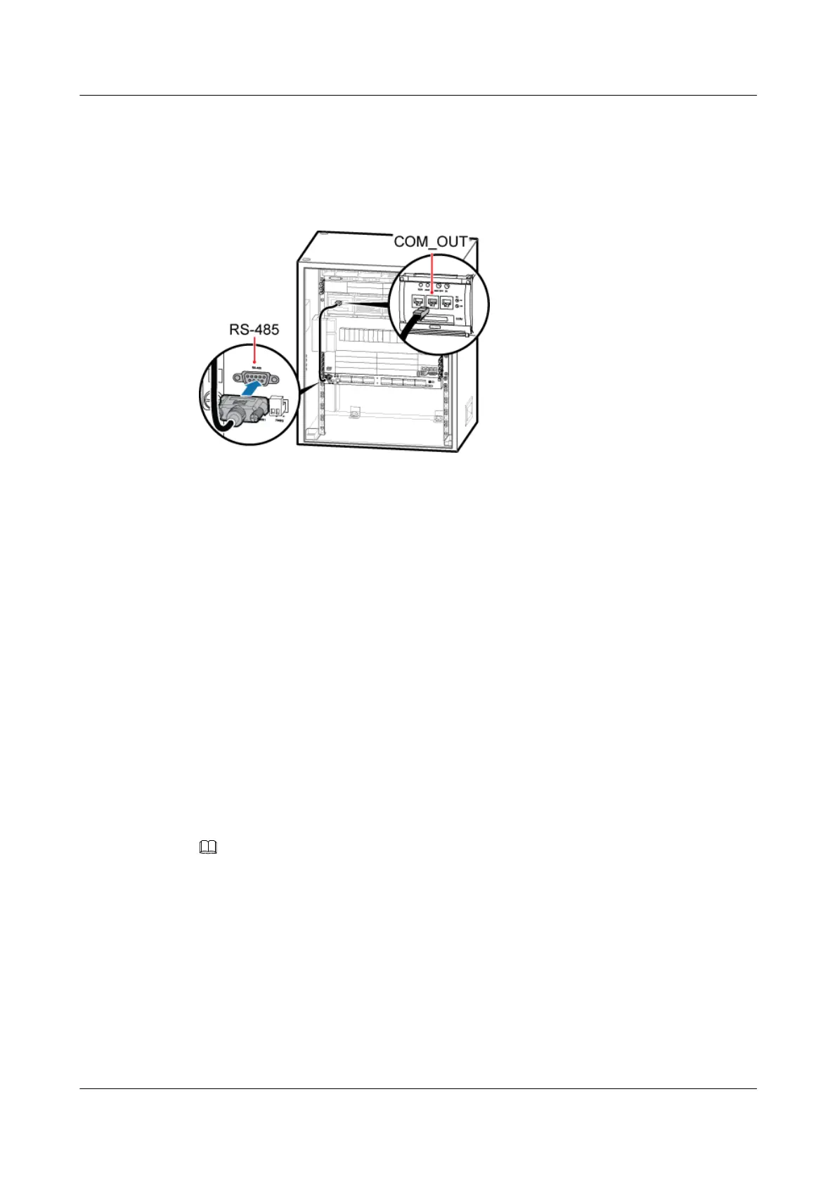
Step 3 Figure 6-57 shows the connection of the EMUA monitoring signal cable.
Figure 6-57 Installing the EMUA monitoring signal cable
1. Connect the DB9 male connector at one end of the signal cable to the wiring terminal labeled
RS-485 in left of the EMUA panel.
2. Connect the RJ45 connector at the other end of the signal cable to COM_OUT of the PMU
in the cabinet.
Step 4 Route the cables by referring to 6.5.1 Cabling Requirements and use cable ties to bind the
cables.
Step 5 Attach labels to the installed power cable and monitoring signal cable. For details, see Attaching
a Sign Plate Label and Attaching an L-Shaped Label.
----End
6.4.7 Installing the GPS Surge Protector
This section describes the procedure and precautions for installing the GPS surge protector and
related cables.
Context
NOTE
Only a dual-satellite receiver needs to be installed onsite.
Procedure
Step 1 Remove the two M3 screws on the panel, and then pull out the USCU, as shown in Figure
6-58.
DBS3900 (Ver.B)
Installation Guide
6 Outdoor Scenario with AC Power Supply (BBU Installed
in an APM30H)
Issue 06 (2011-09-15) Huawei Proprietary and Confidential
Copyright © Huawei Technologies Co., Ltd.
63
 Loading...