1. Connect the liquid pipe stop valve first, and then the gas pipe stop valve.
2. Tighten the liquid pipe stop valve using a 27# torque wrench to a torque of 35–37 N·m.
Tighten the gas pipe stop valve using a 36# torque wrench to a torque of 50–52 N·m
3. When tightening a stop valve using a torque wrench, secure the hex nut of the active
connector at the welded copper pipe to prevent the copper pipe from turning and further
deforming as the stop valve is being tightened.
4. Ensure that you tighten the valve to the specified torque. The failure torque for the nut of the
liquid pipe stop valve is 70 N·m and that for the nut of the gas pipe stop valve is 100 N·m.
The torque greater than the failure torque will damage the screw thread.
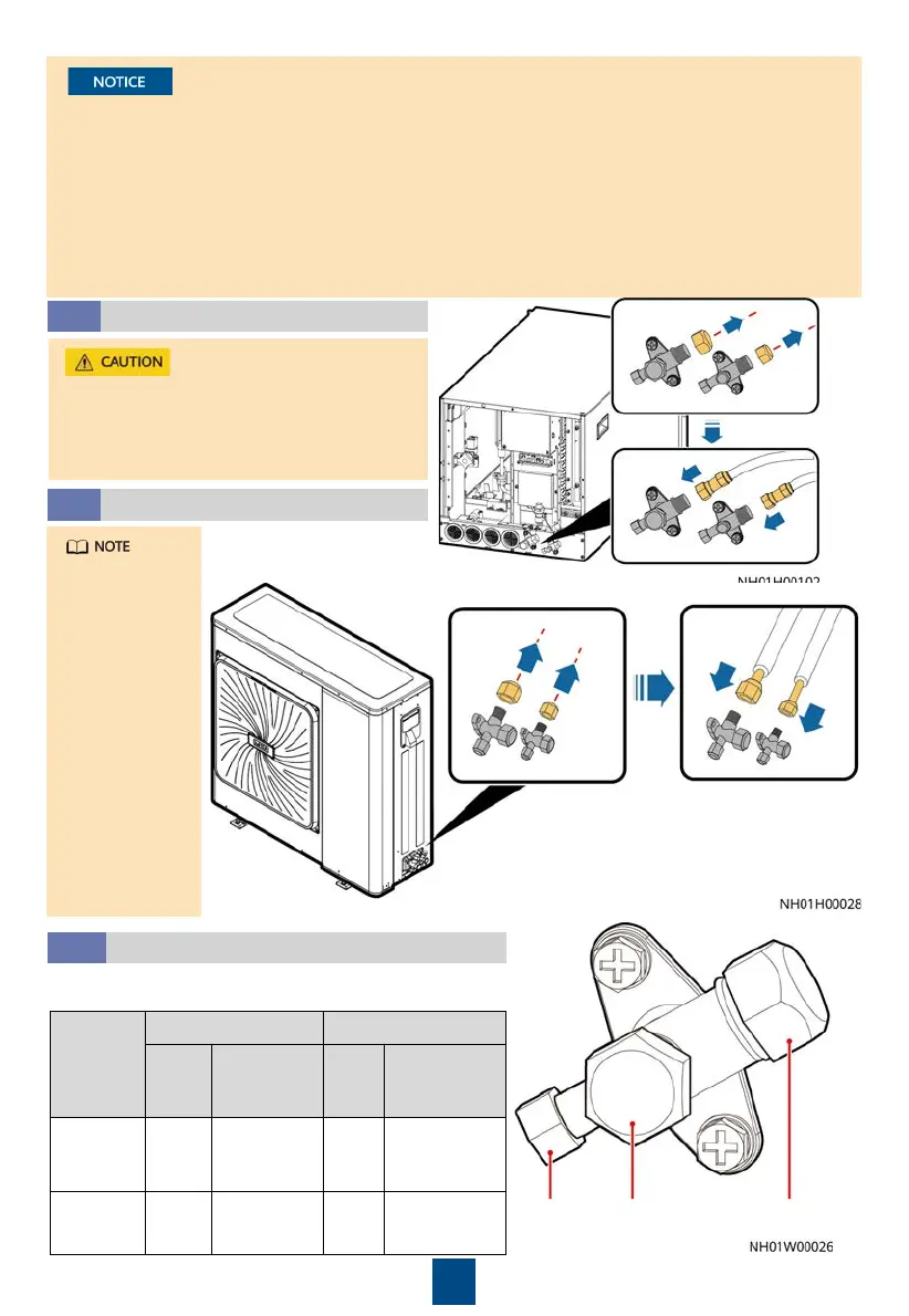
Connecting the Indoor Unit
6.3
Wrap the gas pipe stop valve, liquid pipe
stop valve and the pipes connected to the
stop valves with thermal insulation foam
(the thickness is 5 mm).
13
Connecting the Outdoor Unit
6.4
The outdoor
unit has been
charged
R410A
refrigerant
before
delivery. To
avoid
refrigerant
leaks, do not
open the
outdoor unit
stop valve
before
vacuumizing is
complete.
Installing Nuts
6.5
When installing a needle valve nut and rear cover
nut, use the torque specified in the following table.
Needle
valve nut
Rear
cover nut
Black plastic nut
Item
Needle Valve Nut Rear Cover Nut
Nut
Size
Tightening
Torque
(N·m)
Nut
Size
Tightening
Torque
(N·m)
Liquid
pipe stop
valve
17# 10 19# 15–17
Gas pipe
stop valve
17# 10 30# 20–22
 Loading...