59
• A cabinet electronic clasp lock is installed at the front and rear doors of each cabinet
respectively. The address for the cabinet electronic clasp lock on the front door is an odd
number, and that for the cabinet electronic clasp lock on the rear door is an even number.
• The cabinet electronic clasp locks of odd-numbered cabinets are connected in series. The
addresses start from 1, and a maximum of 12 cabinet electronic clasp locks can be connected
in series.
• The cabinet electronic clasp locks of even-numbered cabinets are connected in series. The
addresses start from 1, and a maximum of 12 cabinet electronic clasp locks can be connected
in series.
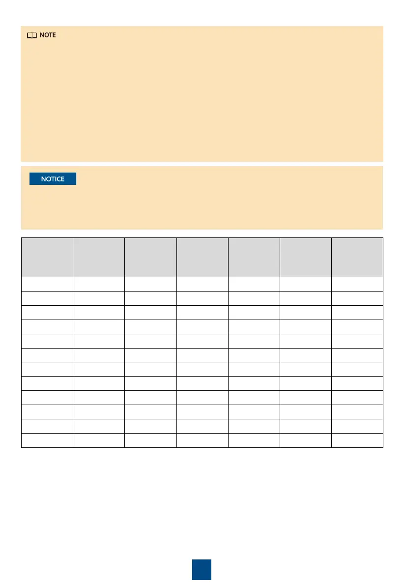
• Set a device address for a cabinet electronic clasp lock by operating the DIP switch on the
cabinet electronic clasp lock. Toggle switches 1 to 6 specify the device address in binary
mode. ON indicates 1, and OFF indicates 0.
Address
Toggle
Switch 1
Toggle
Switch 2
Toggle
Switch 3
Toggle
Switch 4
Toggle
Switch 5
Toggle
Switch 6
1 ON OFF OFF OFF OFF OFF
2 OFF ON OFF OFF OFF OFF
3 ON ON OFF OFF OFF OFF
4 OFF OFF ON OFF OFF OFF
5 ON OFF ON OFF OFF OFF
6 OFF ON ON OFF OFF OFF
7 ON ON ON OFF OFF OFF
8 OFF OFF OFF ON OFF OFF
9 ON OFF OFF ON OFF OFF
10 OFF ON OFF ON OFF OFF
11 ON ON OFF ON OFF OFF
12 OFF OFF ON ON OFF OFF
2. Add the cabinet electronic clasp locks.
a. Log in to the ECC800-Pr
o WebUI as an administrator.
b. Create a cabinet view in Smart Module View on the home page.
c. Add a cabinet electronic clasp lock.
• To close the door, rotate the lock handle vertically downwards.
• The numbers indicate the toggle switch settings of the electronic clasp lock.
• The RS485_R toggle switches of the electronic locks must be set to ON for cabinets at the
ends.
3. Commission the cabinet electronic clasp locks.
 Loading...