17
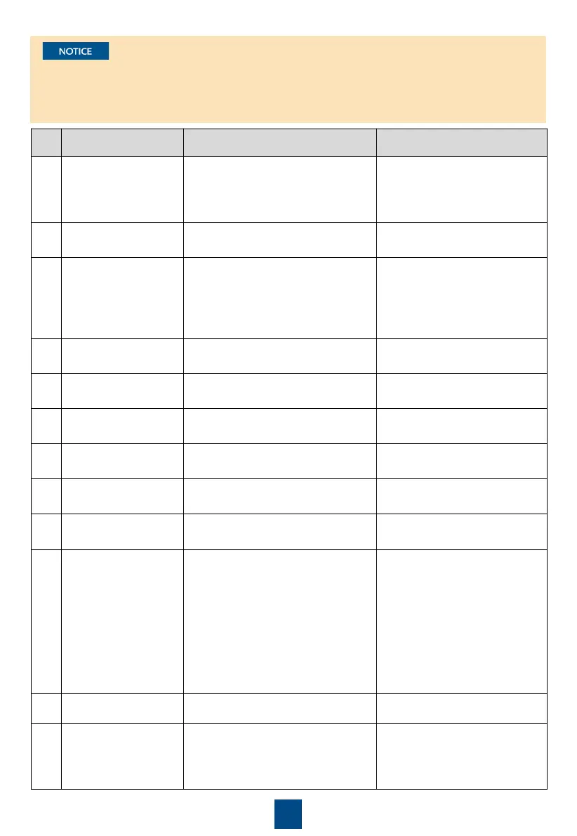
No. Cable Name From To
1
Outdoor unit power
cable (3 x 6 mm
2
)
L (converged cabinet XT2-5, XT2-6,
XT2-7 and XT2-8 correspond to
outdoor units 4, 3, 2, and 1,
respectively.), N bar, PE bar
L, N, and PE ports on the electric
control box of the outdoor unit
2
Control unit input
power cable
L and N on the indoor unit INPUT1 port on the control unit
3
Signal cable for the
indoor and outdoor
units (3-core outdoor
shielded cable, 16–22
AWG)
X2.1, X2.2, and X2.3 ports on the
indoor unit
P, Q, and E ports on the electric
control box of the outdoor unit
4 J1 cable
X101, X102, X103 and X104 ports on
the indoor unit
J1 port on the control unit
5 J2 cable
X101, X102, X103 and X104 ports on
the indoor unit
J2 port on the control unit
6
Control unit output
power cable
X1.1, X1.2, X1.3, and FU1-FU3 ports
on the indoor unit
OUT1 port on the control unit
7 J3 cable
X101, X102, X103 and X104 ports on
the indoor unit
J3 port on the control unit
8 J4 cable
X101, X102, X103 and X104 ports on
the indoor unit
J4 port on the control unit
9
Temperature/Humidity
(T/H) sensor cable
RS485/12V port on the control unit T/H sensor
10 ECC800-Pro cable FE-1 port on the control unit
• If the smart ETH gateway is
configured, connect the cable
to the PoE port on the smart
ETH gateway.
• If no smart ETH gateway is
configured, connect the cable
to the WAN_2 port on the
ECC800-Pro.
11 Ground cable Ground point on the control unit IT cabinet ground copper bar
12
Indoor unit power
cable (3 x 4 mm
2
)
L (converged cabinet XT2-9, XT2-10,
XT2-11 and XT2-12 correspond to
indoor units 4, 3, 2, and 1,
respectively.), N bar, PE bar
L, N, and PE ports on the indoor
unit
•
Do not pull cables J1, J2, J3, and J4 and their terminals casually. Ensure that the cables are
connected securely.
•
The length of the signal cable for the indoor and outdoor units cannot exceed 200 meters.
•
The signal cable should be shielded, and the shield layer should be grounded.
 Loading...