EasyManuals Logo
Home>IDEC>Controller>FC4A-C16R2

IDEC FC4A-C16R2 User Manual

IDEC FC4A-C16R2
525 pages
To Next Page IconTo Next Page
To Previous Page IconTo Previous Page
Page #100 background imageLoading...
Page #100 background image
3: INSTALLATION AND WIRING
3-6 « FC4A MICROSMART USERS MANUAL »
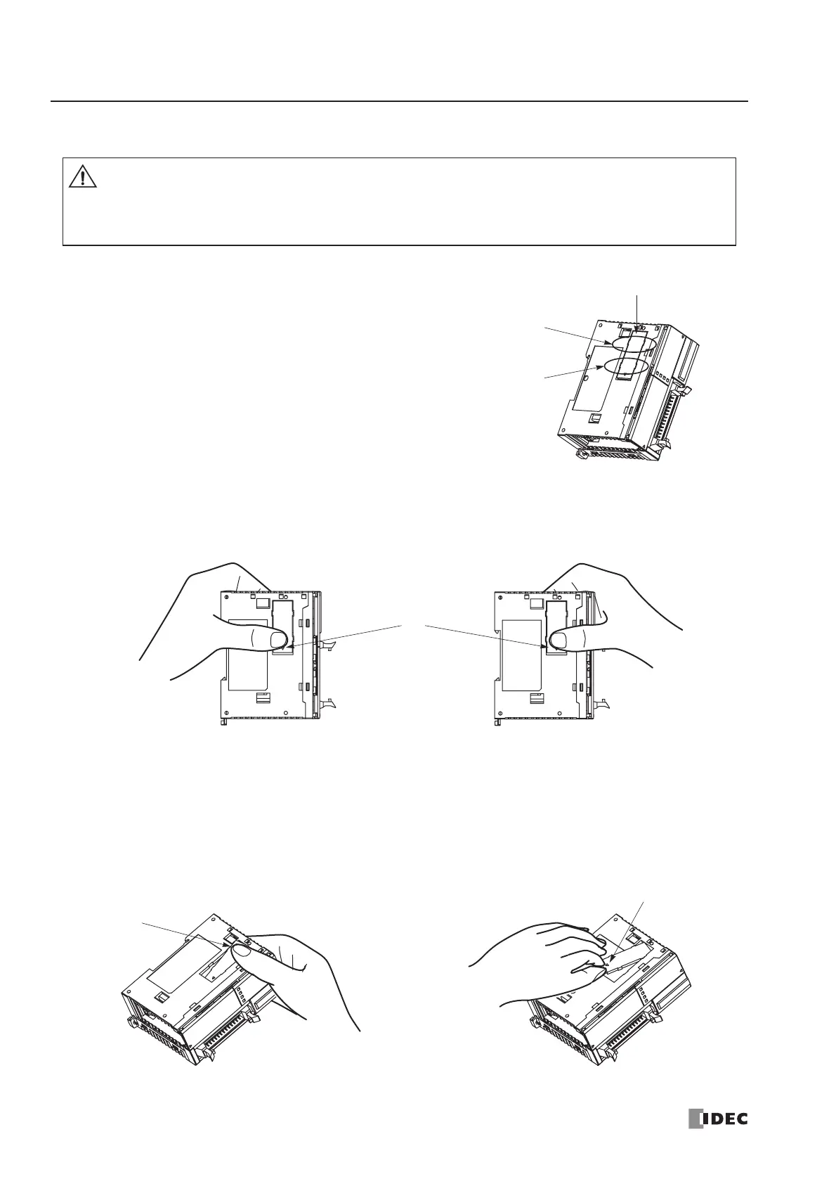
Removing the Communication Connector Cover
Before mounting a communication module or HMI base module next
to the slim type CPU module, the communication connector cover
must be removed from the CPU module. Break the communication
connector cover on the slim type CPU module as described below.
1. Carefully push in the communication connector cover at position (1) to break bridges A as shown in either figure
below.
2. The other end (2) of the communication connector cover will come out as shown at left below. Push in this end.
3. Then, the opposite end (3) will come out. If the end does not come out, insert a thin screwdriver into the gap and pull
out the end (3).
Hold the communication connector cover at (3), and pull off the communication connector cover to break bridges B.
Caution
When using a thin screwdriver to pull out the communication connector cover, insert the screw-
driver carefully and do not damage the electronic parts inside the CPU module.
When first pushing in the communication connector cover to break, take care not to injure your
finger.
Bridges B
Bridges A
C
ommun
i
cat
i
on
Connector Cover
(1)
(2)
(3)

Table of Contents

Questions and Answers:

Question and Answer IconNeed help?

Do you have a question about the IDEC FC4A-C16R2 and is the answer not in the manual?

IDEC FC4A-C16R2 Specifications

General IconGeneral
BrandIDEC
ModelFC4A-C16R2
CategoryController
LanguageEnglish

Related product manuals