13: SHIFT / ROTATE INSTRUCTIONS
13-6 « FC4A MICROSMART USER’S MANUAL »
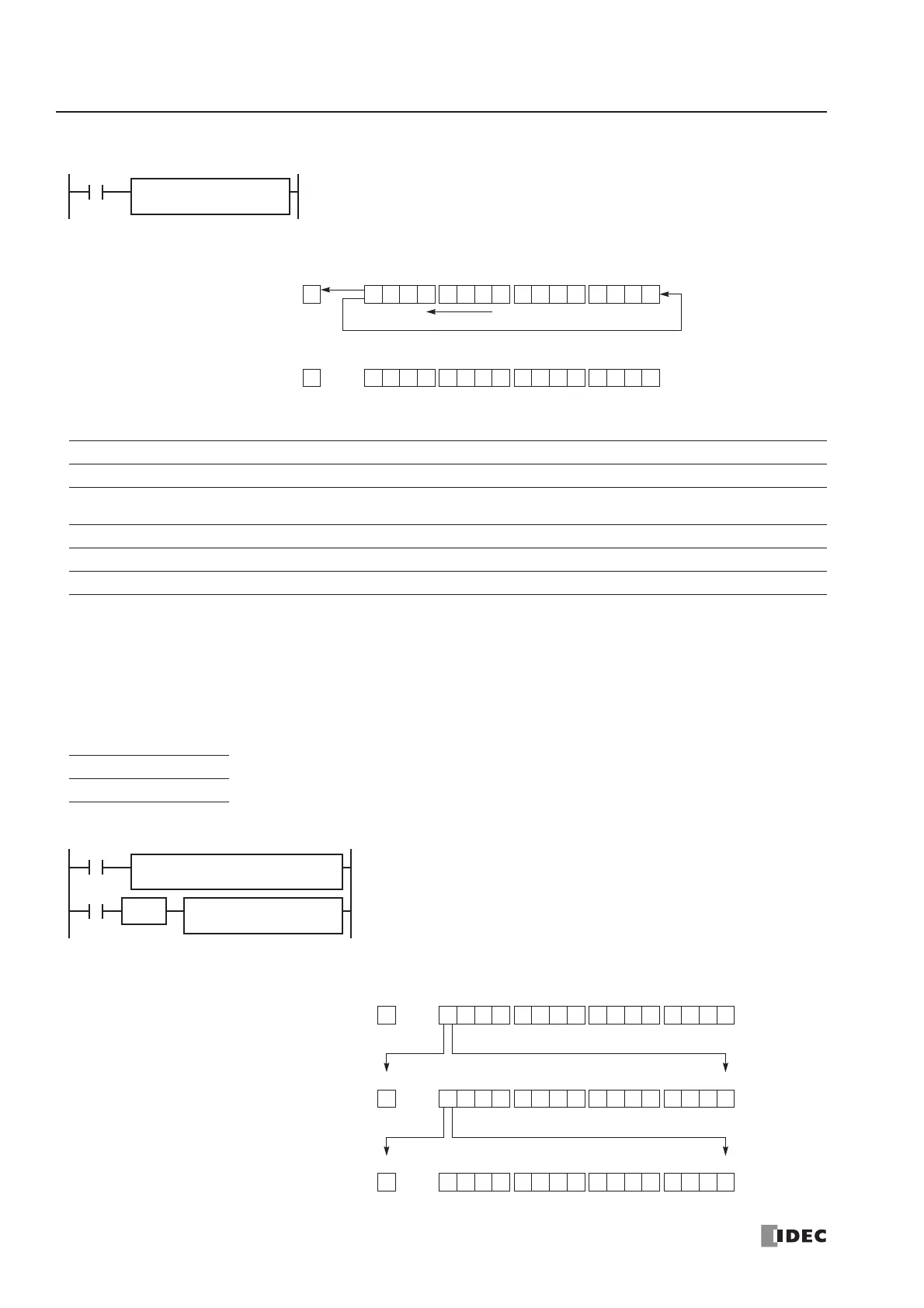
ROTL (Rotate Left)
Applicable CPU Modules
Valid Operands
For the valid operand number range, see pages 6-1 and 6-2.
▲ Internal relays M0 through M1277 can be designated as S1. Special internal relays cannot be designated as S1.
The quantity of bits to rotate can be 1 through 15.
Since the ROTL instruction is executed in each scan while input is on, a pulse input from a SOTU or SOTD instruction
should be used as required.
Valid Data Types
Example: ROTL
FC4A-C10R2/C FC4A-C16R2/C FC4A-C24R2/C FC4A-D20K3/S3 FC4A-D20RK1/RS1 & FC4A-D40K3/S3
XXX X X
Operand Function I Q M R T C D Constant Repeat
S1 (Source 1) Data for bit rotation — X ▲ X——X — —
bits Quantity of bits to rotate ——————— 1-15 —
W (word) I (integer)
X—
Before rotation: 1 0 1010 1 0 1 1 1101 0 0
CY
M8003
MSB LSB
S1
1After rotation: 0 1010 1 0 1 1 1101 0 0
CY
M8003
MSB LSB
S1
1
Rotate to the left
S1
*****
bits
**
When input is on, 16-bit data of the designated source operand S1 is rotated to
the left by the quantity of bits designated by operand bits.
The result is set to the source operand S1, and the last bit status rotated out is
set to a carry (special internal relay M8003).
ROTL(W)
When bits to rotate = 1
When a bit operand such as Q (output), M (internal relay), or R (shift register) is designated
as the source, 16 points are used.
When a word operand such as D (data register) is designated as the source, 1 point is used.
Before rotation: D10 = 40966
1 1 0000 0 0 0 0 1100 0 0
CY
M8003
MSB LSB
D10
After first rotation: D10 = 16397
Bits to rotate = 1
After second rotation: D10 = 32794
1 0 0 0001 0 0 0 0 0100 1 1
CY
M8003
MSB LSB
D10
0 1 0 0000 0 0 0 0 1010 1 0
CY
M8003
MSB LSB
D10
M8120
REP
M8120 is the initialize pulse special internal relay.
When the CPU starts operation, the MOV (move) instruction sets 40966
to data register D10.
Each time input I0 is turned on, 16-bit data of data register D10 is rotated
to the left by 1 bit as designated by operand bits.
The status of the MSB is set to a carry (special internal relay M8003).
SOTU
I0
S1 –
40966
D1 –
D10
S1
D10
bits
1
ROTL(W)
MOV(W)
 Loading...


