9: MOVE INSTRUCTIONS
« FC4A MICROSMART USER’S MANUAL » 9-7
BMOV (Block Move)
Applicable CPU Modules
Valid Operands
For the valid operand number range, see pages 6-1 and 6-2.
▲ Internal relays M0 through M1277 can be designated as D1. Special internal relays cannot be designated as D1.
When T (timer) or C (counter) is used as S1 or N-W, the timer/counter current value is read out. When T (timer) or C
(counter) is used as D1, the data is written in as a preset value which can be 0 through 65535.
Make sure that the last source data determined by S1+N–1 and the last destination data determined by D1+N–1 are within
the valid operand range. If the derived source or destination operand is out of the valid operand range, a user program exe-
cution error will result, turning on special internal relay M8004 and the ERR LED on the CPU module.
Valid Data Types
Special Internal Relay M8024: BMOV/WSFT Executing Flag
While the BMOV or WSFT is executed, M8024 turns on. When completed, M8024 turns off. If the CPU is powered down
while executing BMOV or WSFT, M8024 remains on when the CPU is powered up again.
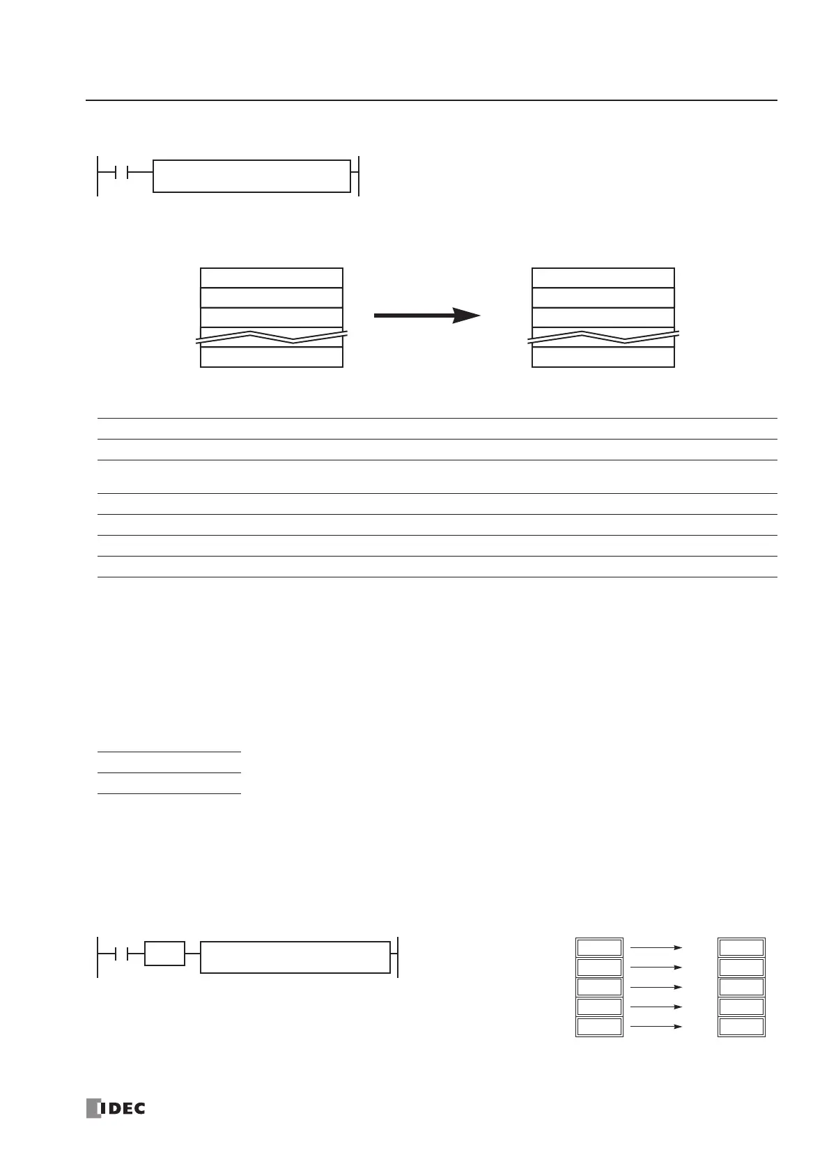
Example: BMOV
FC4A-C10R2/C FC4A-C16R2/C FC4A-C24R2/C FC4A-D20K3/S3 FC4A-D20RK1/RS1 & FC4A-D40K3/S3
——— — X
Operand Function I Q M R T C D Constant Repeat
S1 (Source 1) First operand number to move XXXXXXX — —
N-W (N words) Quantity of blocks to move XXXXXXX X —
D1 (Destination 1) First operand number to move to — X ▲ XXXX — —
W (word) I (integer)
X—
S1, S1+1, S1+2, ... , S1+N–1 → D1, D1+1, D1+2, ... , D1+N–1
When input is on, N blocks of 16-bit word data starting with operand
designated by S1 are moved to N blocks of destinations, starting with
operand designated by D1. N-W specifies the quantity of blocks to move.
BMOV(W) S1
*****
D1
*****
N-W
*****
First 16-bit dataS1
Second 16-bit dataS1+1
Third 16-bit dataS1+2
Nth 16-bit dataS1+N–1
N blocks of 16-bit data
First 16-bit dataD1
Second 16-bit dataD1+1
Third 16-bit dataD1+2
Nth 16-bit dataD1+N–1
N blocks of 16-bit data
Block Move
When a bit operand such as I (input), Q (output), M (internal relay), or R (shift register) is
designated as the source, N-W, or destination, 16 points are used.
When a word operand such as T (timer), C (counter), or D (data register) is designated as the
source, N-W, or destination, 1 point is used.
D1
D20
D10 through D14 → D20 through D24
When input I0 is turned on, data of 5 data registers starting with D10 desig-
nated by source operand S1 is moved to 5 data registers starting with D20
designated by destination operand D1.
12
D11
1998
D10
25
D12
S1
D10
N-W
5
I0
BMOV(W)
12
D13
30
D14
12
D21
1998
D20
25
D22
12
D23
30
D24
SOTU
 Loading...


