26: COMPUTER LINK COMMUNICATION
26-2 « FC4A MICROSMART USER’S MANUAL »
Programming WindLDR
In the 1:1 computer link system, a computer can be connected to either port 1 or 2 on the MicroSmart CPU module. In the
1:N computer link system, a computer must be connected to port 2 on the CPU module and every CPU module must have
a unique device number 0 through 31. The Communication page in the Function Area Settings must be programmed for
each station in the computer link system. If required, communication parameters can also be changed.
Since these settings relate to the user program, the user program must be downloaded to the MicroSmart after changing
any of these settings.
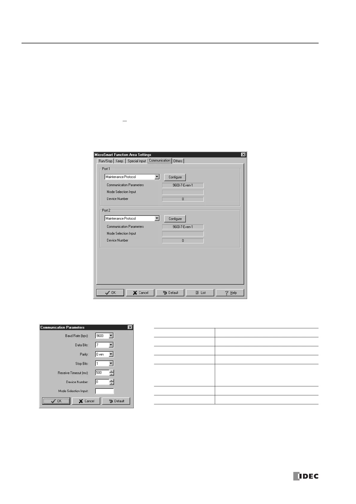
1. From the WindLDR menu bar, select Configure > Function Area Settings. The Function Area Setting dialog box
appears.
2. Click the Communication tab, and select Maintenance Protocol in the Port 1 or 2 pull-down list.
3. Click the Configure button. The Communication Parameters dialog box appears. Change settings, if required.
4. Click the OK button.
Baud Rate (bps) 1200, 2400, 4800, 9600, 19200
Data Bits 7 or 8
Parity None, Odd, Even
Stop Bits 1 or 2
Receive Timeout (ms)
10 to 2540 (10-msec increments)
(Receive timeout is disabled when 2550
is selected.)
Device Number 0 to 31
Mode Selection Input Any input number
Note: Only when the mode selection input is turned on, the selected communication parameters are enabled.
Otherwise, default communication parameters take effect; 9600 bps, 7 data bits, even parity, 1 stop bit,
receive timeout 500 msec.
 Loading...


