7: BASIC INSTRUCTIONS
« FC4A MICROSMART USER’S MANUAL » 7-3
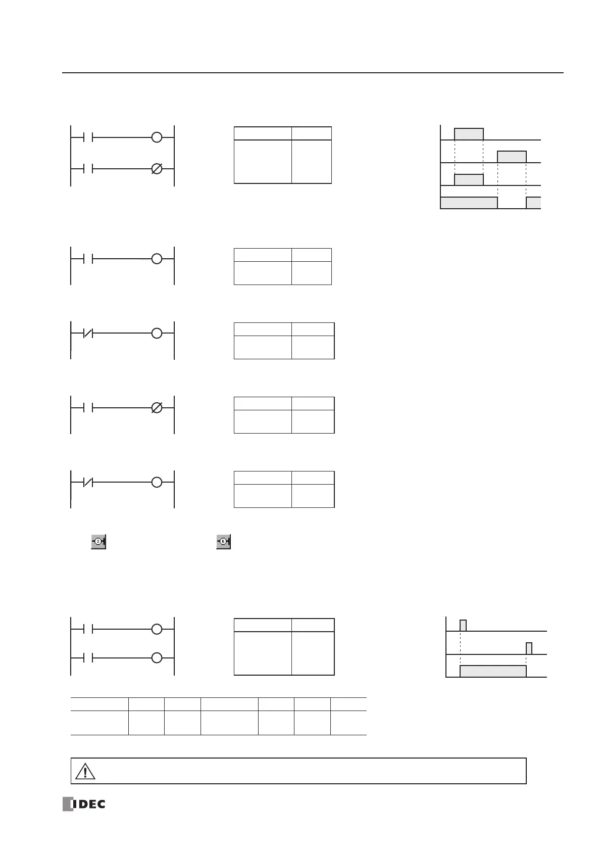
Examples: LOD (Load), OUT (Output), and NOT
SET and RST (Reset)
The SET and RST (reset) instructions are used to set (on) or reset (off) outputs, internal relays, and shift register bits. The
same output can be set and reset many times within a program. SET and RST instructions operate in every scan while the
input is on.
Ladder Diagram
I0
Instruction Data
LOD
OUT
LOD
OUTN
I0
Q0
I1
Q1
Program List
I0
ON
OFF
I1
ON
OFF
Q0
ON
OFF
Q1
ON
OFF
Timing Chart
Q0
Q1I1
Ladder Diagram
M2
Instruction Data
LOD
OUT
M2
Q0
Program List
Ladder Diagram
Q0
Instruction Data
LODN
OUT
Q0
Q1
Program List
Ladder Diagram
T0
Instruction Data
LOD
OUTN
T0
Q2
Program List
Ladder Diagram
Instruction Data
LODN
OUT
C1
Q10
Program List
C1
Q0
Q10
Q1
Q2
Ladder Diagram
I0
I1
I0
ON
OFF
I1
ON
OFF
Q0
ON
OFF
Timing Chart
Instruction Data
LOD
SET
LOD
RST
I0
Q0
I1
Q0
Program List
Valid Operands
The valid operand range depends on the CPU module type. For details, see pages 6-1 and 6-2.
Instruction I Q M T C R
SET
RST
— 0-307
0-1277
8000-8077
——0-127
Q0
S
Q0
R
Caution
• For restrictions on ladder programming of SET and RST instructions, see page 29-22.
 Loading...


