13: SHIFT / ROTATE INSTRUCTIONS
« FC4A MICROSMART USER’S MANUAL » 13-5
WSFT (Word Shift)
Applicable CPU Modules
Valid Operands
For the valid operand number range, see pages 6-1 and 6-2.
When T (timer) or C (counter) is used as S1 or S2, the timer/counter current value is read out.
Valid Data Types
Special Internal Relay M8024: BMOV/WSFT Executing Flag
While the BMOV or WSFT is executed, M8024 turns on. When completed, M8024 turns off. If the CPU is powered down
while executing BMOV or WSFT, M8024 remains on when the CPU is powered up again.
Example: WSFT
FC4A-C10R2/C FC4A-C16R2/C FC4A-C24R2/C FC4A-D20K3/S3 FC4A-D20RK1/RS1 & FC4A-D40K3/S3
——— — X
Operand Function I Q M R T C D Constant Repeat
S1 (Source 1) Source data for word shift XXXXXXX X —
S2 (Source 2) Quantity of blocks to shift XXXXXXX X —
D1 (Destination 1) First operand number to shift —————— X — —
W (word) I (integer)
X—
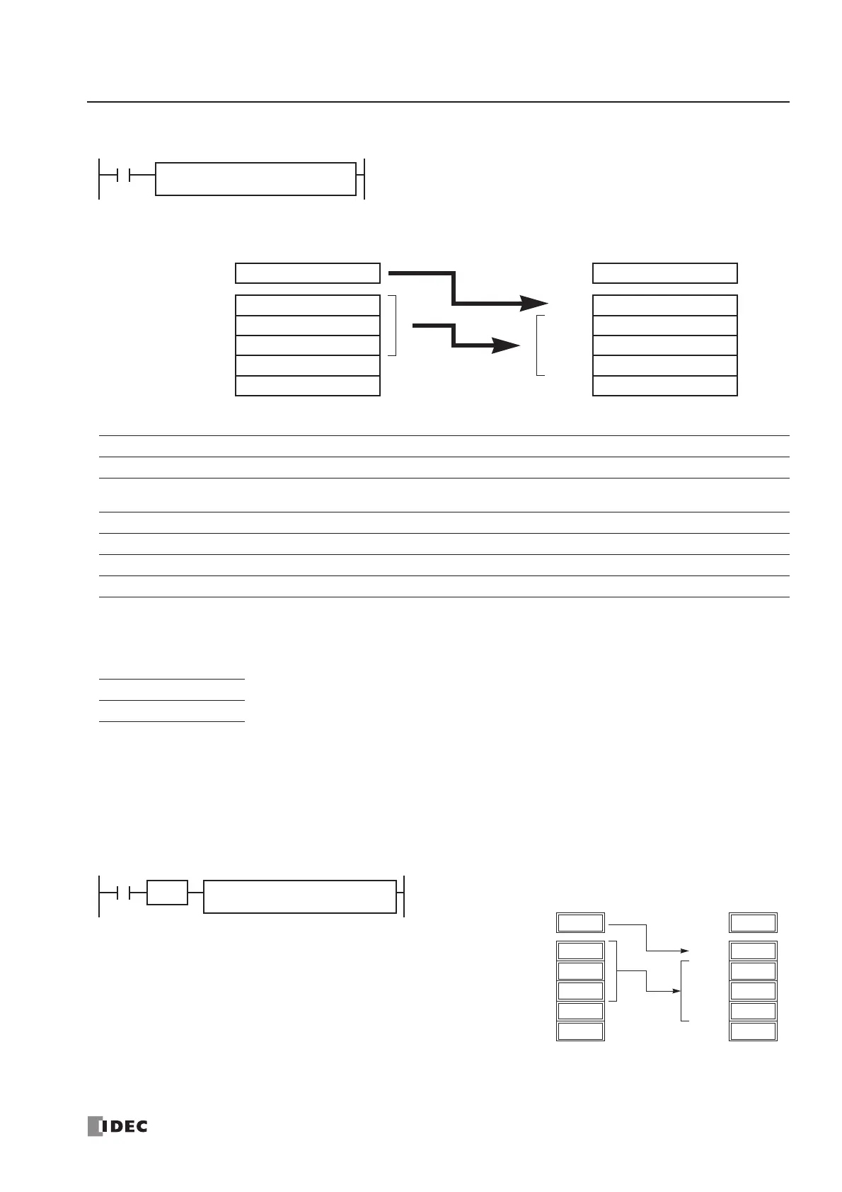
When input is on, N blocks of 16-bit word data starting with operand
designated by D1 are shifted up to the next 16-bit positions. At the
same time, the data designated by operand S1 is moved to operand
designated by D1. S2 specifies the quantity of blocks to move.
WSFT S1
*****
D1
*****
S2
*****
When S2 = 3 (quantity of blocks to shift)
First 16-bit dataD1+0
Second 16-bit dataD1+1
Third 16-bit dataD1+2
Fifth 16-bit dataD1+4
Fourth 16-bit dataD1+3
S1 dataD1+0
First 16-bit dataD1+1
Second 16-bit dataD1+2
Fifth 16-bit dataD1+4
Third 16-bit dataD1+3
3 blocks (S2)
16-bit dataS1 16-bit dataS1
When a bit operand such as I (input), Q (output), M (internal relay), or R (shift register) is
designated as source S1 or S2, 16 points are used.
When a word operand such as T (timer), C (counter), or D (data register) is designated as
source S1 or S2, 1 point is used.
D100 through D102 → D101 through D103
D10 → D100
When input I0 is turned on, data of 3 data registers starting with
D100 designated by destination operand D1 is shifted to the next
data registers. Data of data register D10 designated by source oper-
and S1 is moved to D100 designated by destination operand D1.
SOTU
I0
S1
D10
D1
D100
WSFT S2
3
2222
D101
1111
D100
3333
D102
4444
D103
5555
D104
1111
D101
12345
D100
2222
D102
3333
D103
5555
D104
12345
D10
12345
D10
Before shift: After first shift:
 Loading...


