2: MODULE SPECIFICATIONS
« FC4A MICROSMART USER’S MANUAL » 2-23
Input Modules
Digital input modules are available in 8-, 16-, and 32-point DC input modules and an 8-point AC input module with a
screw terminal block or plug-in connector for input wiring. All DC input modules accept both sink and source DC input
signals.
The input modules can be connected to the all-in-one 24-I/O type CPU module and all slim type CPU modules to expand
input terminals. The all-in-one 10- and 16-I/O type CPU modules cannot connect input modules.
Input Module Type Numbers
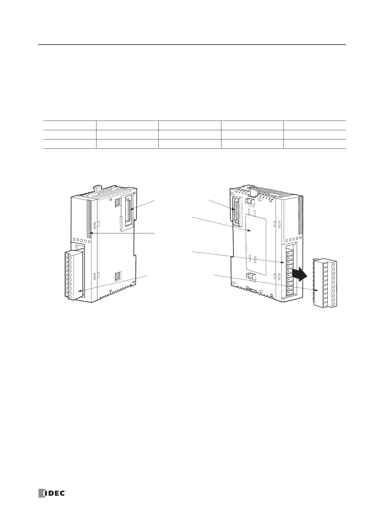
Parts Description
(1) Expansion Connector Connects to the CPU and other I/O modules.
(The all-in-one 10- and 16-I/O type CPU modules cannot be connected.)
(2) Module Label Indicates the input module Type No. and specifications.
(3) LED Indicator Turns on when a corresponding input is on.
(4) Terminal No. Indicates terminal numbers.
(5) Cable Terminal/Connector Five different terminal/connector styles are available for wiring.
Module Name 8-point DC Input 16-point DC Input 32-point DC Input 8-point AC Input
Screw Terminal FC4A-N08B1 FC4A-N16B1 — FC4A-N08A11
Connector — FC4A-N16B3 FC4A-N32B3 —
 Loading...


