14: DATA CONVERSION INSTRUCTIONS
« FC4A MICROSMART USER’S MANUAL » 14-7
BTOA (BCD to ASCII)
Applicable CPU Modules
Valid Operands
For the valid operand number range, see pages 6-1 and 6-2.
When T (timer) or C (counter) is used as S1 or S2, the timer/counter current value is read out.
The quantity of digits to convert can be 1 through 5. Make sure that the quantity of digits designated by S2 is within the
valid range. If the S2 data is out of the valid range, a user program execution error will result, turning on special internal
relay M8004 and the ERR LED.
Since the BTOA instruction is executed in each scan while input is on, a pulse input from a SOTU or SOTD instruction
should be used as required.
Valid Data Types
FC4A-C10R2/C FC4A-C16R2/C FC4A-C24R2/C FC4A-D20K3/S3 FC4A-D20RK1/RS1 & FC4A-D40K3/S3
XXX X X
Operand Function I Q M R T C D Constant Repeat
S1 (Source 1) Binary data to convert XXXXXXX X —
S2 (Source 2) Quantity of digits to convert XXXXXXX 1-5 —
D1 (Destination 1) Destination to store conversion results —————— X — —
W (word) I (integer)
X—
S1 → D1, D1+1, D1+2, D1+3, D1+4
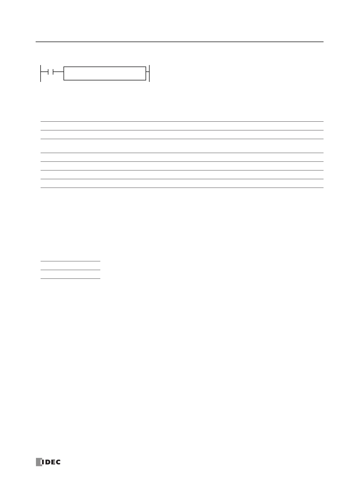
When input is on, the 16-bit binary data designated by S1 is converted
into BCD, and converted into ASCII data. The data is read from the low-
est digit as many as the quantity of digits designated by S2. The result
is stored to the destination starting with the operand designated by D1.
The quantity of digits to convert can be 1 through 5.
BTOA(W) S1
*****
S2
*****
D1
*****
When a bit operand such as I (input), Q (output), M (internal relay), or R (shift register) is
designated as the source, 16 points are used.
When a word operand such as T (timer), C (counter), or D (data register) is designated as the
source or destination, 1 point is used.
 Loading...


