14: DATA CONVERSION INSTRUCTIONS
« FC4A MICROSMART USER’S MANUAL » 14-11
ENCO (Encode)
Applicable CPU Modules
Valid Operands
For the valid operand number range, see pages 6-1 and 6-2.
▲ Internal relays M0 through M1277 can be designated as D1. Special internal relays cannot be designated as D1.
Valid values for Bits to designate the quantity of bits searched are 1 through 256. Make sure that the search area designated
by S1 plus Bits is within the valid value range. If the source data is out of the valid range, a user program execution error
will result, turning on special internal relay M8004 and the ERR LED.
Since the ENCO instruction is executed in each scan while input is on, a pulse input from a SOTU or SOTD instruction
should be used as required.
Examples: ENCO
FC4A-C10R2/C FC4A-C16R2/C FC4A-C24R2/C FC4A-D20K3/S3 FC4A-D20RK1/RS1 & FC4A-D40K3/S3
——— — X
Operand Function I Q M R T C D Constant Repeat
S1 (Source 1) First bit to start search XXXX——X — —
D1 (Destination 1) Destination to store search results — X ▲ X——X — —
Bits Quantity of bits searched ——————— 1-256 —
When input is on, a bit which is on is sought. The search begins at S1 until the
first point which is set (on) is located. The quantity of points from S1 to the first
set point (offset) is stored to the destination designated by operand D1.
If no point is on in the searched area, 65535 is stored to D1.
ENCO
Bits
S1
*****
D1
*****
D1
D100
S1
M4
I0
ENCO
64
M17 M0
M37
M20
M57
M40
M77
M60
M97
M80
M117 M100
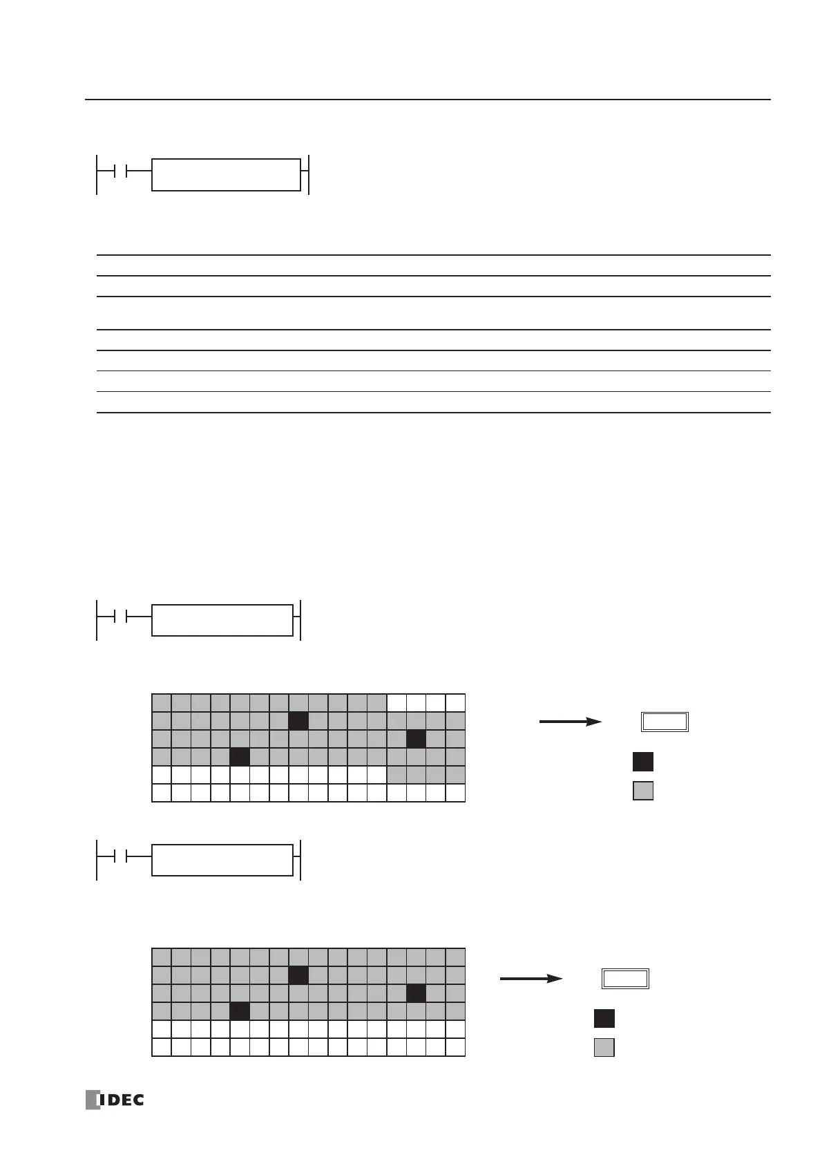
When input I0 is on, a bit which is on is sought in 64 bits starting at internal
relay M4 designated by operand S1.
Since internal relay M30 is the first point that is on, the offset from the first
search point is 20, and 20 is stored to data register D100 designated by oper-
and D1.
ON
Searched area
20
D100
D1
D100
S1
D10
I1
ENCO
64
Bit 15 14 13 12 11 10 9876543210
D10
D11
D12
D13
D14
D15
When input I1 is on, a bit which is on is sought in 64 bits starting at bit 0 of data
register D10 designated by operand S1.
Since bit 8 of data register D11 is the first point that is on, the offset from the
first search point is 24, and 24 is stored to data register D100 designated by
operand D1.
ON
Searched area
24
D100
 Loading...


