5: SPECIAL FUNCTIONS
5-32 « FC4A MICROSMART USER’S MANUAL »
HMI Module
This section describes the functions and operation of the optional HMI module (FC4A-PH1). The HMI module can be
installed on any all-in-one type CPU module, and also on the HMI base module mounted next to any slim type CPU mod-
ule. The HMI module makes it possible to manipulate the RAM data in the CPU module without using the Online menu
options in WindLDR. For details about the specifications of the HMI module, see page 2-59.
HMI module functions include:
• Displaying timer/counter current values and changing timer/counter preset values
• Displaying and changing data register values
• Setting and resetting bit operand statuses, such as inputs, outputs, internal relays, and shift register bits
• Displaying and clearing error data
• Starting and stopping the PLC
• Displaying and changing calendar/clock data (only when using the clock cartridge)
• Confirming changed timer/counter preset values
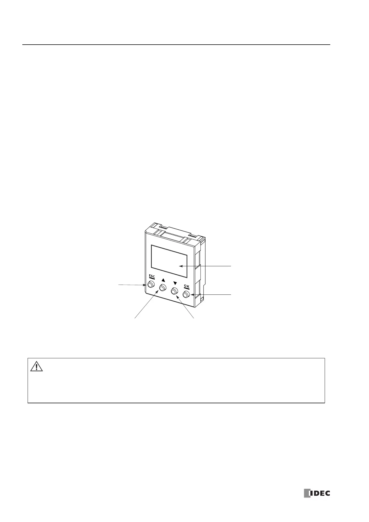
Parts Description
ESC Button
Cancels the current operation,
and returns to the immediately
preceding operation.
▲
Button
Scrolls up the menu, or increments the
selected operand number or value.
▼ Button
Scrolls down the menu, or decrements the
selected operand number or value.
OK Button
Goes into each control screen, or
enters the current operation.
Display Screen
The liquid crystal display shows
menus, operands, and data.
Caution
• Power up the MicroSmart CPU module after installing the HMI module. If the HMI module is
installed or removed while the MicroSmart is powered up, the HMI module may fail to operate
correctly.
• If an invalid operand or a value over 65535 is entered, the display screen flashes to signal an error.
When an error screen displays, press the ESC button and repeat the correct key operation.
 Loading...


