« FC4A MICROSMART USER’S MANUAL » 15-1
15: WEEK PROGRAMMER INSTRUCTIONS
Introduction
WKTIM instructions can be used as many as required to turn on and off designated outputs and internal relays at predeter-
mined times and days of the week.
Once the internal calendar/clock is set, the WKTIM instruction compares the predetermined time with the clock data in the
clock cartridge. When the preset time is reached, internal relay or output designated as destination operand is turned on or
off as scheduled. For setting the calendar/clock, see page 15-5.
For the specifications of the clock cartridge, see page 2-67.
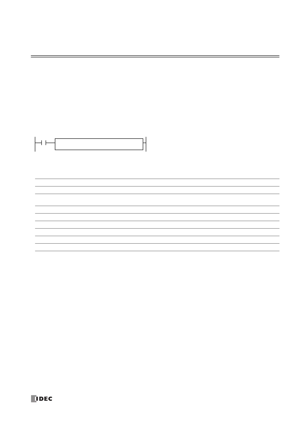
WKTIM (Week Timer)
Applicable CPU Modules
Valid Operands
For the valid operand number range, see pages 6-1 and 6-2.
▲ Internal relays M0 through M1277 can be designated as D1. Special internal relays cannot be designated as D1.
MODE — Week table output control (0 through 2)
0: Disable the week table
When the current day and time reach the presets for S1, S2, and S3, the designated output or internal relay is turned
on or turned off. Set 0 for MODE when the WKTBL is not used; the WKTBL instruction is ignored even if it is pro-
grammed.
1: Additional days in the week table
When the current time reaches the hour/minute comparison data set for S2 or S3 on the special day programmed in
the WKTBL, the designated output or internal relay is turned on (S2) or turned off (S3).
2: Skip days in the week table
On the special day programmed in the WKTBL, the designated output or internal relay is not turned on or off, even
when the current day and time reach the presets for S1, S2, and S3.
Note: When 1 or 2 is set for MODE, program special days in the week table using the WKTBL instruction, followed by
the WKTIM instruction. If the WKTBL instruction is not programmed when 1 or 2 is set for MODE in the WKTIM instruc-
tion, a user program execution error will result, turning on special internal relay M8004 and the ERR LED on the CPU
module. The same error also occurs if the WKTIM instruction is executed before the WKTBL instruction.
FC4A-C10R2/C FC4A-C16R2/C FC4A-C24R2/C FC4A-D20K3/S3 FC4A-D20RK1/RS1 & FC4A-D40K3/S3
XXX X X
Operand Function I Q M R T C D Constant Repeat
MODE Week table output control ——————— 0-2 —
S1 (Source 1) Day of week comparison data —————— X 0-127 —
S2 (Source 2) Hour/minute comparison data to turn on —————— X 0-2359 —
S3 (Source 3) Hour/minute comparison data to turn off —————— X 0-2359 —
D1 (Destination 1) Comparison ON output — X ▲ ———— — —
ing on the week table output control designated by MODE.
 Loading...


