10: DATA COMPARISON INSTRUCTIONS
10-4 « FC4A MICROSMART USER’S MANUAL »
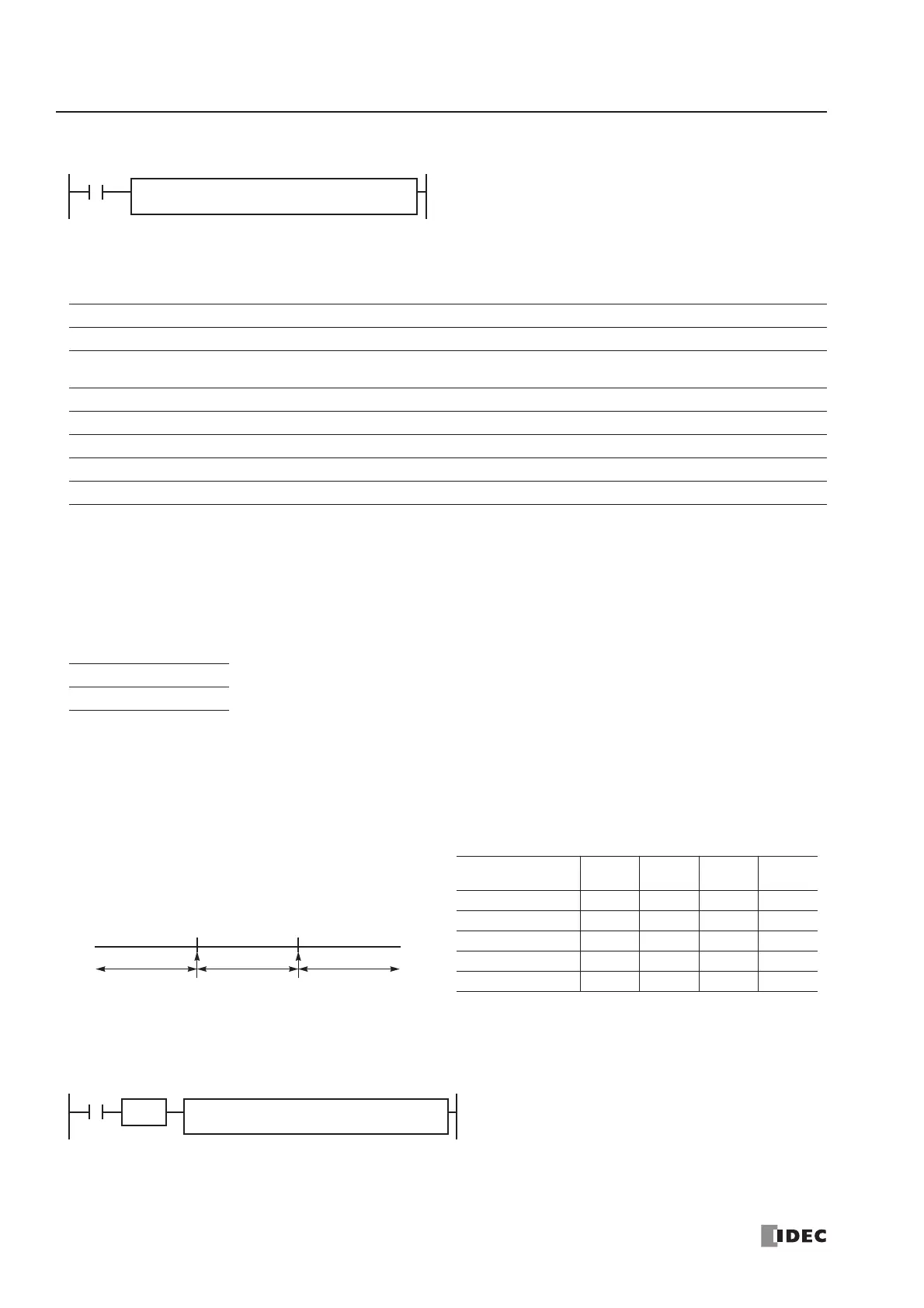
ICMP>= (Interval Compare Greater Than or Equal To)
Applicable CPU Modules
Valid Operands
For the valid operand number range, see pages 6-1 and 6-2.
▲ Internal relays M0 through M1277 can be designated as D1. Special internal relays cannot be designated as D1.
When T (timer) or C (counter) is used as S1, S2, or S3, the timer/counter current value is read out.
When the data of S1 is smaller than that of S3 (S1 < S3), a user program execution error will result, turning on special
internal relay M8004 and ERR LED on the CPU module.
Valid Data Types
Special Internal Relays M8150, M8151, and M8152 in ICMP>=
Three special internal relays are provided to indicate the comparison result of the ICMP>= instruction. Depending on the
result, one of the three special internal relays turns on. S1 must always be greater than or equal to S3 (S1 ≥ S3).
When more than one ICMP>= or CMP= instruction is used, M8150, M8151, or M8152 indicates the result of the instruc-
tion that was executed last.
Example: ICMP>=
FC4A-C10R2/C FC4A-C16R2/C FC4A-C24R2/C FC4A-D20K3/S3 FC4A-D20RK1/RS1 & FC4A-D40K3/S3
——— — X
Operand Function I Q M R T C D Constant Repeat
S1 (Source 1) Data to compare XXXXXXX X —
S2 (Source 2) Data to compare XXXXXXX X —
S3 (Source 3) Data to compare XXXXXXX X —
D1 (Destination 1) Comparison output — X ▲ ———— — —
W (word) I (integer)
XX
S1 ≥ S2 ≥ S3 → D1 on
When input is on, the 16-bit data designated by S1, S2, and
S3 are compared. When the condition is met, destination
operand D1 is turned on. When the condition is not met, D1 is
turned off.
ICMP>=(*) S1
*****
S2
*****
S3
*****
D1
*****
When a bit operand such as I (input), Q (output), M (internal relay), or R (shift register) is
designated as the source, 16 points are used.
When a word operand such as T (timer), C (counter), or D (data register) is designated as the
source, 1 point is used.
The destination uses only one output or internal relay regardless of the selected data type.
When S2 > S1, M8150 turns on.
When S2 < S3, M8151 turns on.
When S1 > S2 > S3, M8152 turns on.
S2 Value M8150 M8151 M8152
D1
Status
(1) S2 < S3 OFF ON OFF OFF
(2) S2 = S3 OFF OFF OFF ON
(3) S3 < S2 < S1 OFF OFF ON ON
(4) S2 = S1 OFF OFF OFF ON
(5) S2 > S1 ON OFF OFF OFF
S2
S3
S1
M8151 M8152 M8150
(2)(1) (3) (5)(4)
Small Large
D1
M10
When input I0 is turned on, data of data registers D10, D11, and D12 designated by source operands S1, S2, and S3 are
compared. When the condition is met, internal relay M10 designated by destination operand D1 is turned on. When the con
dition is not met, M10 is turned off.
S1
D10
I0
ICMP>=(W) S2
D11
S3
D12
SOTU
D10 ≥ D11 ≥ D12 → M10 goes on
 Loading...


