13: SHIFT / ROTATE INSTRUCTIONS
13-4 « FC4A MICROSMART USER’S MANUAL »
BCDLS (BCD Left Shift)
Applicable CPU Modules
Valid Operands
For the valid operand number range, see pages 6-1 and 6-2.
When T (timer) or C (counter) is used as S2, the timer/counter current value is read out.
The quantity of digits to shift designated as S2 can be 1 through 7.
Make sure that the source data determined by S1 and S1+1 is between 0 and 9999 for each data register. If either source
data is over 9999, a user program execution error will result, turning on special internal relay M8004 and the ERR LED on
the CPU module. When S2 is over 7, a user program execution error will also result.
Example: BCDLS
FC4A-C10R2/C FC4A-C16R2/C FC4A-C24R2/C FC4A-D20K3/S3 FC4A-D20RK1/RS1 & FC4A-D40K3/S3
——— — X
Operand Function I Q M R T C D Constant Repeat
S1 (Source 1) Data for BCD shift —————— X — —
S2 (Source 2) Quantity of digits to shift XXXXXXX 1-7 —
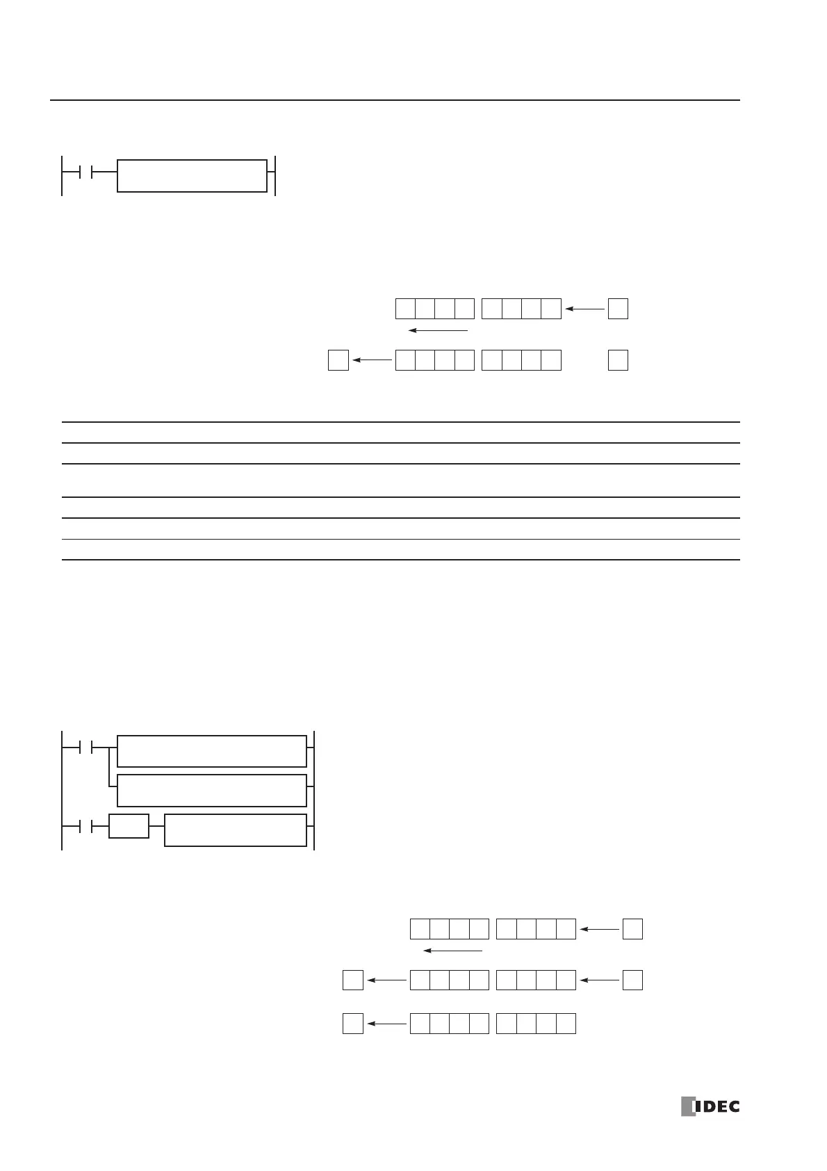
When input is on, the 32-bit binary data designated by S1 is converted into 8
BCD digits, shifted to the left by the quantity of digits designated by S2, and con-
verted back to 32-bit binary data.
Valid values for each of S1 and S1+1 are 0 through 9999.
The quantity of digits to shift can be 1 through 7.
Zeros are set to the lowest digits as many as the digits shifted.
BCDLS S1
*****
Before shift:
After shift:
0 2 31
MSD
S1 S1+1
Shift to the left
LSD
S2
*
4 6 75 0
1 3 42 5 7 060
When S2 = 1 (digits to shift)
0
M8120 is the initialize pulse special internal relay.
When the CPU starts operation, the MOV (move) instructions set 123 and
4567 to data registers D10 and D11, respectively.
Each time input I0 is turned on, the 32-bit binar y data of data registers
D10 and D11 designated by S1 is converted into 8 BCD digits, shifted to
the left by 1 digit as designated by operand S2, and converted back to 32
bit binary data.
Zeros are set to the lowest digits as many as the digits shifted.
Before shift:
After first shift:
0 2 31
D10 D11
Shift to the left
4 6 75 0
1 3 42 5 7 060
REP
SOTU
I0
S1 –
4567
D1 –
D11
S1
D10
S2
1
BCDLS
MOV(W)
M8120
REPS1 –
123
D1 –
D10
MOV(W)
After second shift:
MSD LSD
2 4 53 6 0 071
0
When S2 = 1 (digits to shift)