1: GENERAL INFORMATION
1-4 « FC4A MICROSMART USER’S MANUAL »
System Setup
This section illustrates system setup configurations for using powerful communication functions of the MicroSmart.
User Communication and Modem Communication System
The all-in-one 16- and 24-I/O type MicroSmart CPU modules have port 1 for RS232C communication and port 2 connec-
tor. An optional RS232C or RS485 communication adapter can be installed on the port 2 connector. With an RS232C com-
munication adapter installed on port 2, the 16- or 24-I/O type MicroSmart CPU module can communicate with two
RS232C devices at the same time.
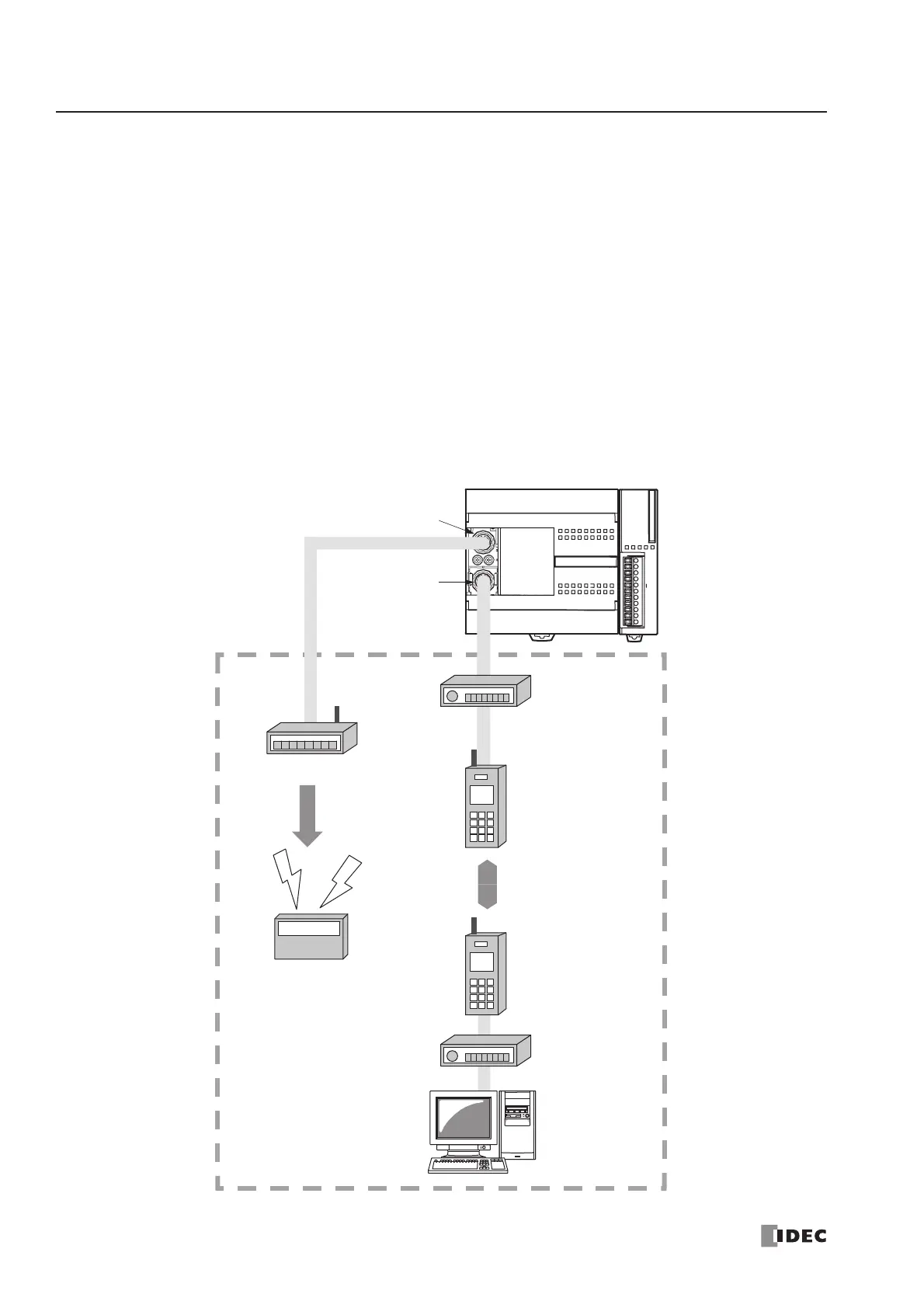
The figure below illustrates a system setup of user communication and modem communication. In this example, the oper-
ating status of a remote machine is monitored on a computer through modems connected to port 2 and the data is trans-
ferred through port 1 to a pager transmitter using the user communication.
The same system can be set up using any slim type CPU module and an optional RS232C communication module.
For details about the user communication, see page 17-1.
For details about the modem mode, see page 27-1.
 Loading...


