15: WEEK PROGRAMMER INSTRUCTIONS
15-6 « FC4A MICROSMART USER’S MANUAL »
Special Internal Relays for Calendar/Clock Data
Example: Setting Calendar/Clock Data
This example demonstrates how to set calendar/clock data using a ladder program. After storing new calendar/clock data
into data registers D8015 through D8021, special internal relay M8020 (calendar/clock data write flag) must be turned on
to set the new calendar/clock data to the clock cartridge.
Adjusting Clock Using a User Program
Special internal relay M8021 (clock data adjust flag) is provided for adjusting the clock data. When M8021 is turned on,
the clock is adjusted with respect to seconds. If seconds are between 0 and 29 for current time, adjustment for seconds will
be set to 0 and minutes remain the same. If seconds are between 30 and 59 for current time, adjustment for seconds will be
set to 0 and minutes are incremented one. M8021 is useful for precise timing which starts at zero seconds.
Example: Adjusting Calendar/Clock Data to 0 Seconds
M8016 Calendar Data Write Flag
When M8016 is turned on, data in data registers D8015 through D8018 (calendar
new data) are set to the clock cartridge installed on the CPU module.
M8017 Clock Data Write Flag
When M8017 is turned on, data in data registers D8019 through D8021 (clock
new data) are set to the clock cartridge installed on the CPU module.
M8020
Calendar/Clock Data
Write Flag
When M8020 is turned on, data in data registers D8015 through D8021 (calen-
dar/clock new data) are set to the clock cartridge installed on the CPU module.
M8120
REP
4
S1 R
D0
MOV(W) D1 R
D8015
I0
SOTU
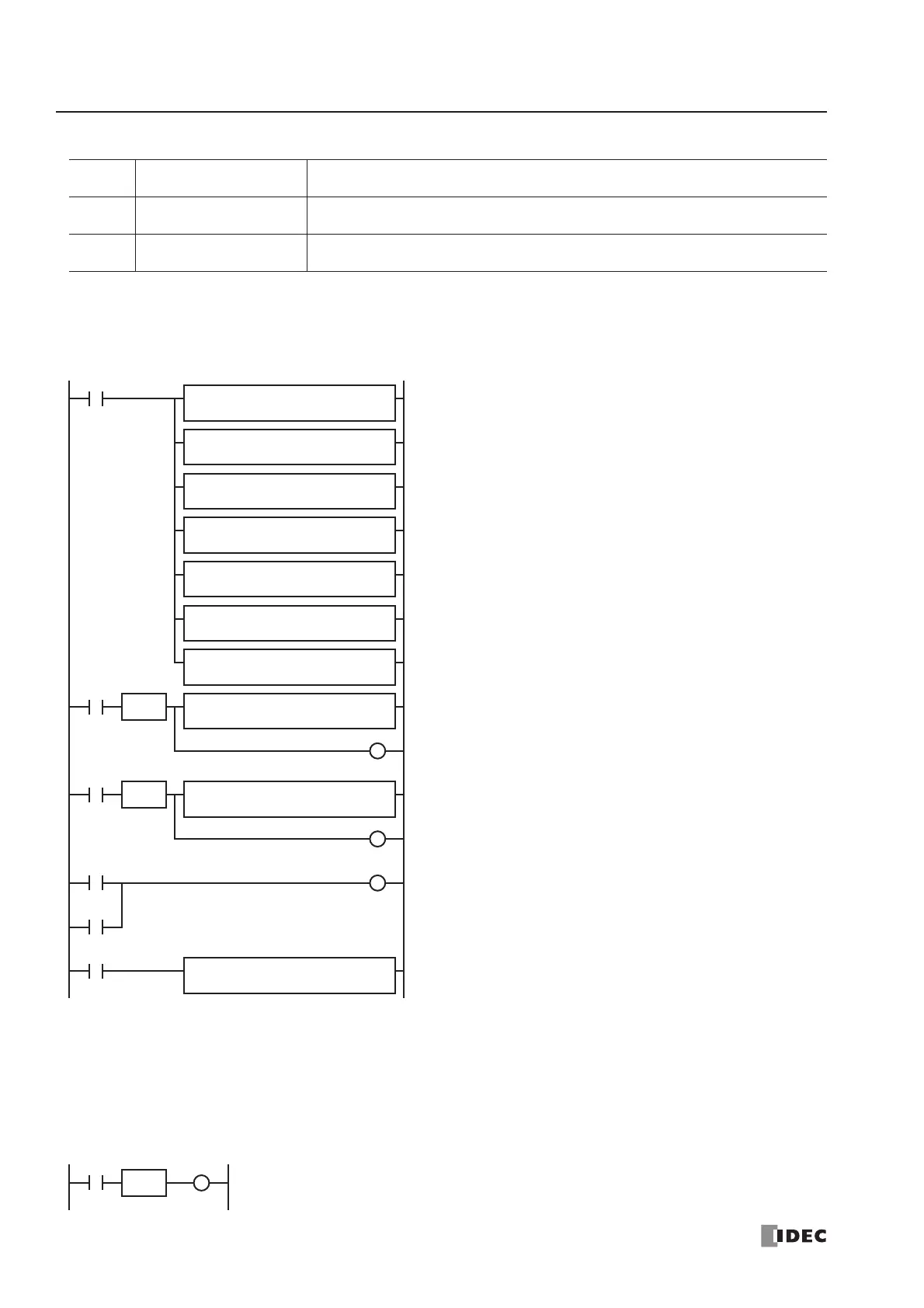
M8120 is the initialize pulse special internal relay.
When the CPU starts, seven MOV(W) instructions store calendar/
clock data to data registers D0 through D6.
When input I0 is turned on, new calendar data (year, month, day,
and day of week) are moved to data registers D8015 through
D8018, and internal relay M0 is turned on for 1 scan time.
When input I1 is turned on, new clock data (hour, minute, and
second) are moved to data registers D8019 through D8021, and
internal relay M1 is turned on for 1 scan time.
When either M0 or M1 is turned on, calendar/clock data write flag
special internal relay M8020 is turned on to set the new calen-
dar/clock data to the clock cartridge.
M8125 is the in-operation output special internal relay.
While the CPU is running, the MOV(W) moves current calendar/
clock data to data registers D10 through D16.
REP
3
S1 R
D4
MOV(W) D1 R
D8019
I1
SOTU
M0
M1
REP
7
S1 R
D8008
MOV(W)
D1 R
D10
M8125
M1
M8020
REPS1 –
0
MOV(W) D1 –
D0
REPS1 –
10
MOV(W)
D1 –
D1
REPS1 –
10
MOV(W) D1 –
D2
REPS1 –
2
MOV(W) D1 –
D3
REPS1 –
9
MOV(W) D1 –
D4
REPS1 –
30
MOV(W) D1 –
D5
REPS1 –
0
MOV(W)
D1 –
D6
M0
and the clock is adjusted with respect to seconds.
 Loading...


