23: INTELLIGENT MODULE ACCESS INSTRUCTIONS
« FC4A MICROSMART USER’S MANUAL » 23-5
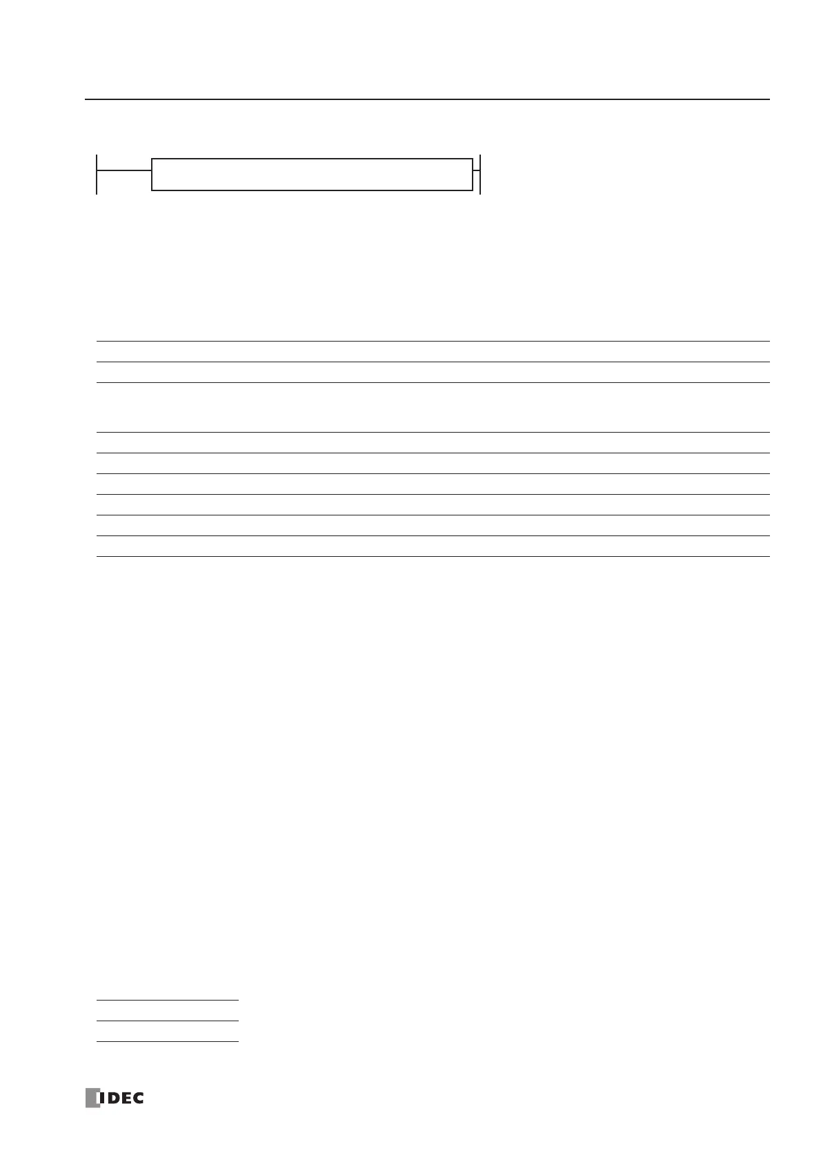
STPA WRITE (Stop Access Write)
Note: STPA READ and STPA WRITE instructions can be used 64 times in a user program. When more than 64 STPA READ
and STPA WRITE instructions are used in a user program, the excess instructions are not executed and error code 7 is
stored in the data register designated as STATUS.
Applicable CPU Modules
Valid Operands (Run Access Write)
For the valid operand number range, see pages 6-1 and 6-2.
DATA: Specify the first operand number to extract the data to write to the intelligent module.
When T (timer) or C (counter) is used as DATA for Stop Access Write, the timer/counter current value is
written to the intelligent module.
All data registers, including special data registers, AS-Interface data registers, and expansion data registers,
can be designated as DATA.
When a constant is designated as DATA, Repeat cannot be selected. For details about the data movement
with or without Repeat, see page 23-7.
STATUS: Specify a data register to store the operating status code. Only data registers D0 through D1299 can be des-
ignated as STATUS. Special data registers, AS-Interface data registers, and expansion data registers cannot
be designated whether the AS-Interface master module is used or not. For status code description, see
page 23-6.
SLOT: Enter the slot number where the intelligent module is mounted. A maximum of seven intelligent modules
can be used.
ADDRESS: Specify the first address in the intelligent module to store the data.
BYTE: Specify the quantity of data to write in bytes.
The STPA WRITE instruction cannot be used in an interrupt program. If used, a user program execution error will result,
turning on special internal relay M8004 and the ERR LED on the CPU module.
If a STPA WRITE instruction is programmed between MCS and MCR instructions, the STPA WRITE instruction is exe-
cuted when the CPU module is stopped regardless whether the input condition for the MCS instruction is on or off. For
MCS and MCR instructions, see page 7-23.
Valid Data Types
FC4A-C10R2/C FC4A-C16R2/C FC4A-C24R2/C FC4A-D20K3/S3 FC4A-D20RK1/RS1 & FC4A-D40K3/S3
—— X X X
Operand Function I Q M R T C D Constant Repeat
DATA First operand number to extract data from XXXXXXX X X
STATUS Operating status code —————— X — —
SLOT Intelligent module slot number ——————— 1-7 —
ADDRESS First address in intelligent module to write data to ——————— 0-127 —
BYTE Bytes of data to write ——————— 1-127 —
W (word) I (integer)
XX
BYTE designates the quantity of data to write.
When a bit operand such as I (input), Q (output), M (internal relay), or R (shift register) is
 Loading...


