11: BINARY ARITHMETIC INSTRUCTIONS
« FC4A MICROSMART USER’S MANUAL » 11-7
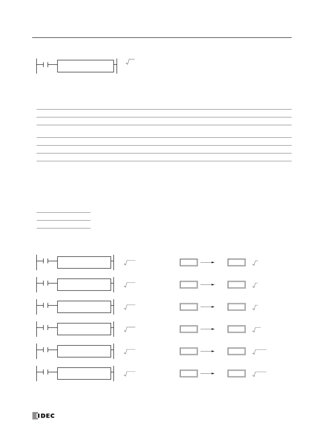
ROOT (Root)
Applicable CPU Modules
Valid Operands
For the valid operand number range, see pages 6-1 and 6-2.
Since the ROOT instruction is executed in each scan while input is on, a pulse input from a SOTU or SOTD instruction
should be used as required.
The ROOT instruction cannot be used in an interrupt program. If used, a user program execution error will result, turning
on special internal relay M8004 and the ERR LED on the CPU module.
Valid Data Types
Examples: ROOT
FC4A-C10R2/C FC4A-C16R2/C FC4A-C24R2/C FC4A-D20K3/S3 FC4A-D20RK1/RS1 & FC4A-D40K3/S3
XXX X X
Operand Function I Q M R T C D Constant Repeat
S1 (Source 1) Binary data —————— X X —
D1 (Destination 1) Destination to store results —————— X — —
W (word) I (integer)
X—
When input is on, the square root of operand designated by S1 is extracted and
is stored to the destination designated by D1.
Valid values are 0 to 65535. The square root is calculated to two decimals, omit-
ting the figures below the second place of decimals.
S1
→ D1
ROOT(W) S1
*****
D1
*****
When a word operand such as D (data register) is designated as the source or destination, 1
point (word data type) is used.
D1
D20
D10 → D20
I0
ROOT(W) S1
D10
3
D11
2
D10
4
D12
9997
D14
9998
D15
173
D21
141
D20
200
D22
9998
D24
9998
D25
Before Execution After Execution
D1
D21
D11 → D21
I1
ROOT(W) S1
D11
D1
D22
D12 → D22
I2
ROOT(W) S1
D12
D1
D24
D14 → D24
I4
ROOT(W) S1
D14
D1
D25
D15 → D25
I5
ROOT(W) S1
D15
2 1.41=
9998 99.98=
9997 99.98=
4 2.00=
3 1.73=
55
D13
741
D23
D1
D23
D13 → D23
I3
ROOT(W) S1
D13
55 7.4161=