« FC4A MICROSMART USER’S MANUAL » 4-1
4: OPERATION BASICS
Introduction
This chapter describes general information about setting up the basic MicroSmart system for programming, starting and
stopping MicroSmart operation, and introduces simple operating procedures from creating a user program using WindLDR
on a computer to monitoring the MicroSmart operation.
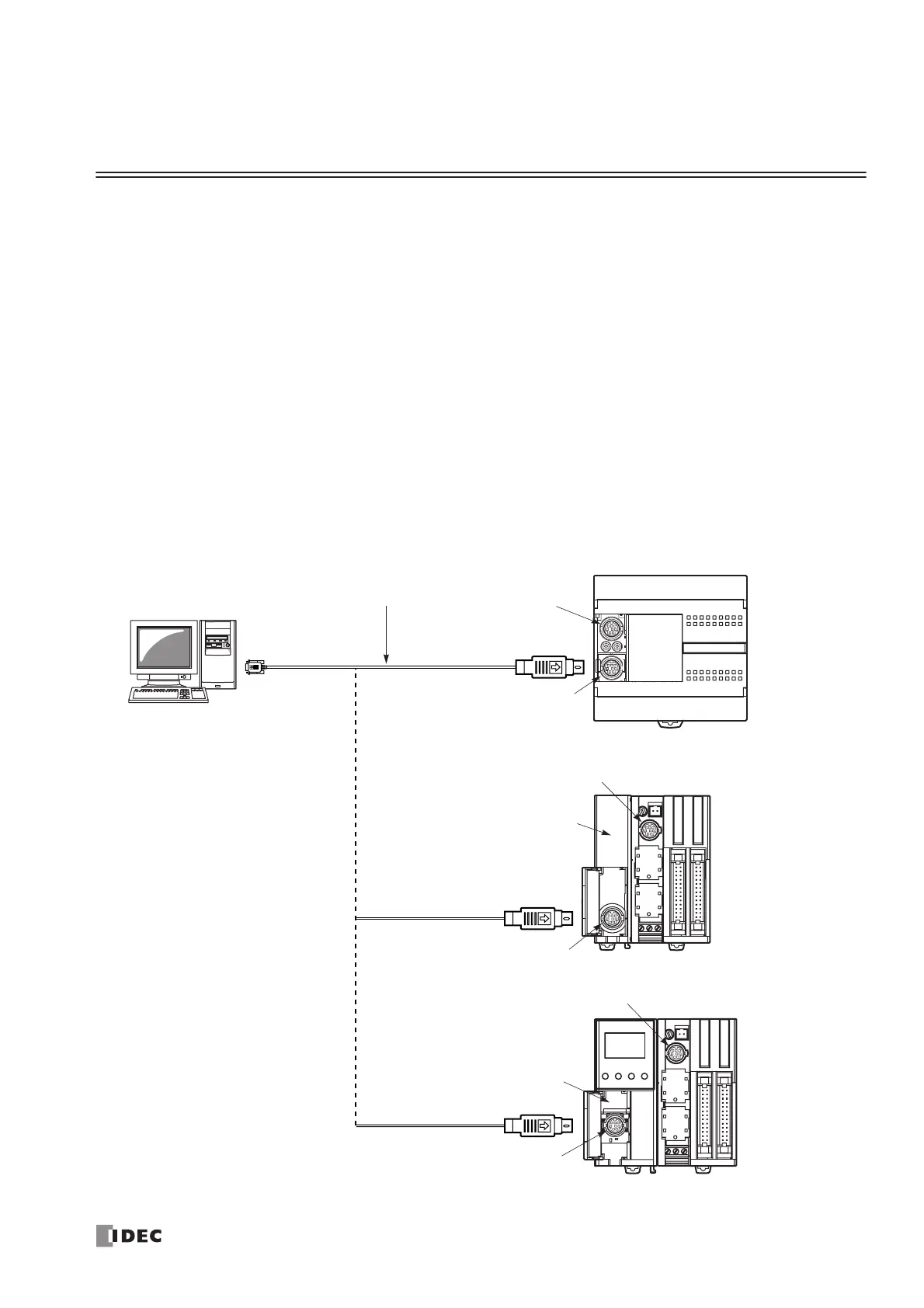
Connecting MicroSmart to PC (1:1 Computer Link System)
The MicroSmart can be connected to a Windows PC in two ways.
Computer Link through Port 1 or Port 2 (RS232C)
When connecting a Windows computer to the RS232C port 1 or port 2 on the MicroSmart CPU module, enable the main-
tenance protocol for the RS232C port using the Function Area Settings in WindLDR. See page 26-2.
To set up a 1:1 computer link system, connect a computer to the CPU module using the computer link cable 4C (FC2A-
KC4C). The computer link cable 4C can be connected to port 1 directly. When connecting the cable to port 2 on the all-in-
one 16- or 24-I/O type CPU module, install an optional RS232C communication adapter (FC4A-PC1) to the port 2 con-
nector. When connecting to port 2 on the slim type CPU module, an optional RS232C communication module (FC4A-
HPC1) is needed. The RS232C communication adapter can also be installed on the HMI base module (FC4A-HPH1).
only; not on the 10-I/O type.
 Loading...


