5: SPECIAL FUNCTIONS
5-6 « FC4A MICROSMART USER’S MANUAL »
High-speed Counter
This section describes the high-speed counter function to count many pulse inputs within one scan. Using the built-in 16-
bit high-speed counter, the MicroSmart counts up to 65535 high-speed pulses from a rotary encoder or proximity switch
without regard to the scan time, compares the current value with a preset value, and turns on the output when the current
value reaches the preset value. This function can be used for simple motor control or to measure lengths of objects.
The all-in-one type CPU modules and slim type CPU modules have different high-speed counter configurations.
High-speed Counters on All-in-One Type CPU Modules
All-in-one type CPU modules have four high-speed counters; HSC1 through HSC4. HSC1 can be used as a two-phase or
single-phase high-speed counter. HSC2 through HSC4 are single-phase high-speed counters. All high-speed counter func-
tions are selected using the Function Area Settings in WindLDR.
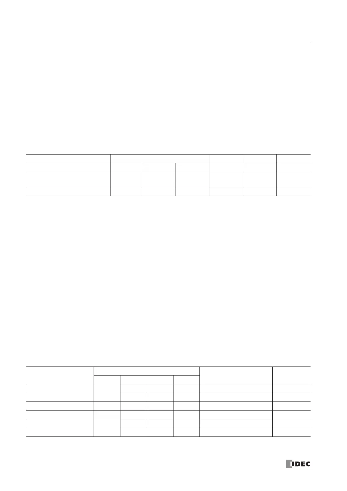
High-speed Counter Operation Modes and Input Terminals (All-in-One Type CPU Modules)
For wiring high-speed counter input signals, use twisted-pair shielded cables.
Two-phase High-speed Counter HSC1 (All-in-One Type CPU Modules)
Two-phase high-speed counter HSC1 operates in the rotary encoder mode, and counts up or down input pulses to input ter-
minals I0 (phase A) and I1 (phase B). When the current value overflows 65535 or underflows 0, a designated comparison
output turns on. Any output terminal available on the CPU module can be designated as a comparison output. When input
I2 (reset input) is turned on, the current value is reset to a predetermined reset value, and the two-phase high-speed counter
counts subsequent input pulses starting at the reset value.
Two special data registers and six special internal relays are assigned to control and monitor the two-phase high-speed
counter operation. The current value is stored in data register D8045 (current value) and is updated every scan. The value
stored in D8046 (reset value) is used as a reset value. When a high-speed counter reset input (I2 or M8032) is turned on,
the current value in D8045 is reset to the value stored in D8046.
The two-phase high-speed counter is enabled while gate input special internal relay M8031 is on and is disabled while
M8031 is off. When current value overflow or underflow occurs while counting up or down, special internal relay M8131
or M8132 turns on in the next scan, respectively. At this point, the D8045 current value is reset to the D8046 reset value for
the subsequent counting cycle. When comparison output reset special internal relay M8030 is turned on, the designated
comparison output is turned off. When reset input I2 is turned on to reset the current value, reset status special internal
relay M8130 turns on in the next scan. When reset input special internal relay M8032 is turned on, M8130 does not turn
on. See page 5-13.
Note: When using input I2 as a phase Z input, set 0 to reset value special data register D8046.
Special Internal Relays for Two-phase High-speed Counter (All-in-One Type CPU Modules)
Note: Special internal relays M8130 through M8132 go on for only one scan.
High-speed Counter No. HSC1 HSC2 HSC3 HSC4
Input Terminal I0 I1 I2 I3 I4 I5
Two-phase High-speed Counter Phase A Phase B
Reset Input
(Phase Z)
———
Single-phase High-speed Counter — Pulse Input Reset Input Pulse Input Pulse Input Pulse Input
Description
High-speed Counter No.
ON Read/Write
HSC1 HSC2 HSC3 HSC4
Comparison Output Reset M8030 — — — Turns off comparison output R/W
Gate Input M8031 — — — Enables counting R/W
Reset Input M8032 — — — Resets the current value R/W
Reset Status M8130 — — — Current value reset by I2 Read only
Current Value Overflow M8131 — — — Overflow occurred Read only
Current Value Underflow M8132 — — — Underflow occurred Read only
 Loading...


