5: SPECIAL FUNCTIONS
5-18 « FC4A MICROSMART USER’S MANUAL »
Catch Input
The catch input function is used to receive short pulses from sensor outputs regardless of the scan time. Input pulses
shorter than one scan time can be received. Four inputs I2 through I5 can be designated to catch a rising or falling edge of
short input pulses, and the catch input statuses are stored to special internal relays M8154 through M8157, respectively.
The Function Area Settings dialog box is used to designate inputs I2 through I5 as a catch input.
Normal input signals to input terminals are read when the END instruction is executed at the end of a scan.
Since these settings relate to the user program, the user program must be downloaded to the MicroSmart after changing
any of these settings.
Catch Input Specifications
Note: Input filter settings have no effect on the catch inputs. For the input filter function, see page 5-24.
Catch Input Terminals and Special Internal Relays for Catch Inputs
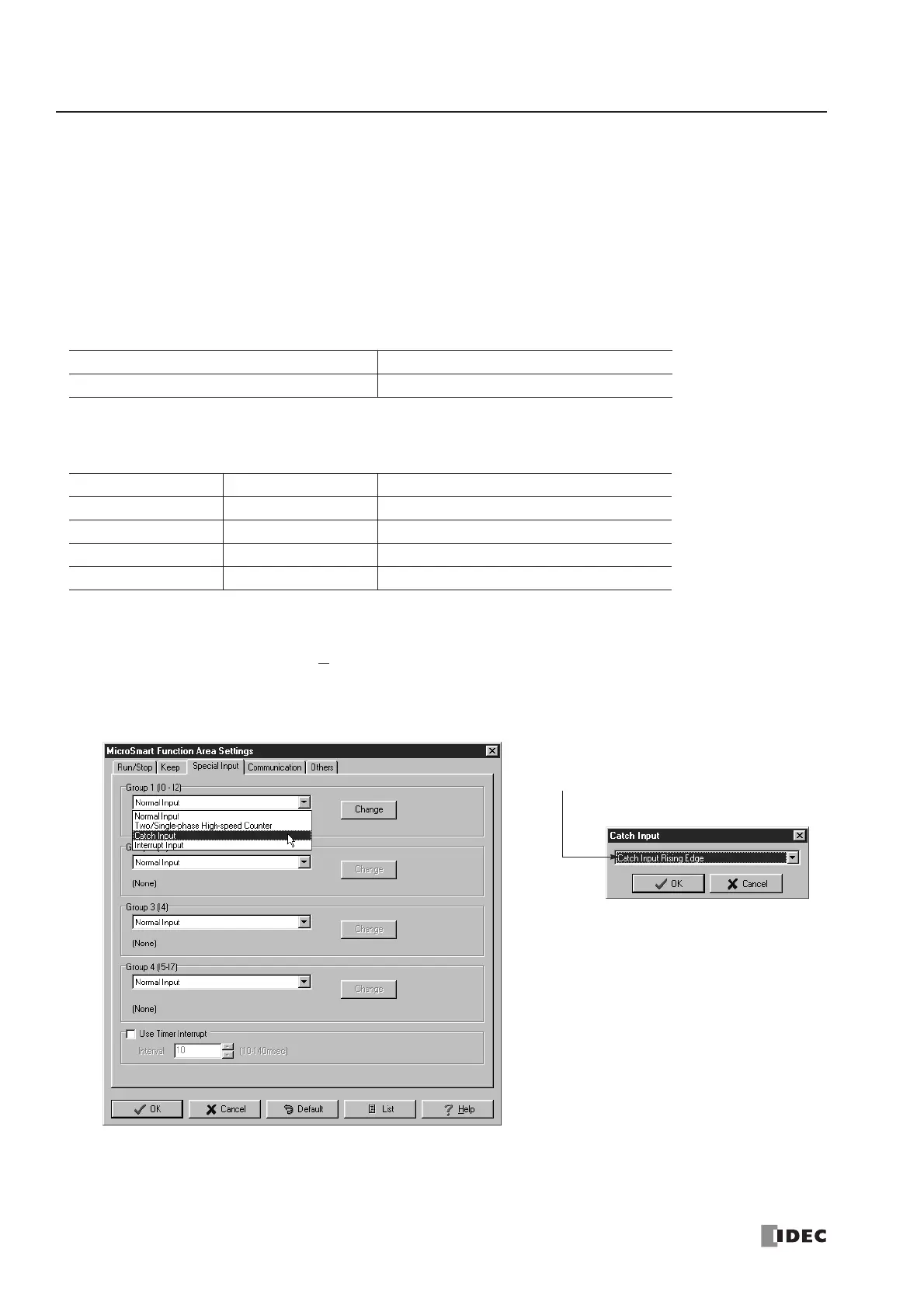
Programming WindLDR
1. From the
WindLDR menu bar, select Configure > Function Area Settings. The Function Area Settings dialog box
appears.
2. Select the Special Input tab.
3. Select Catch Input in the Groups 1 through 4 pull-down list boxes. The Catch Input dialog box appears.
4. Select Catch Input Rising Edge or Catch Input Falling Edge in the pull-down list.
Minimum Turn ON Pulse Width 40 µs
Minimum Turn OFF Pulse Width 150 µs
Group Catch Input No. Special Internal Relay for Catch Input
Group 1 I2 M8154
Group 2 I3 M8155
Group 3 I4 M8156
Group 4 I5 M8157
 Loading...


