7: BASIC INSTRUCTIONS
« FC4A MICROSMART USER’S MANUAL » 7-5
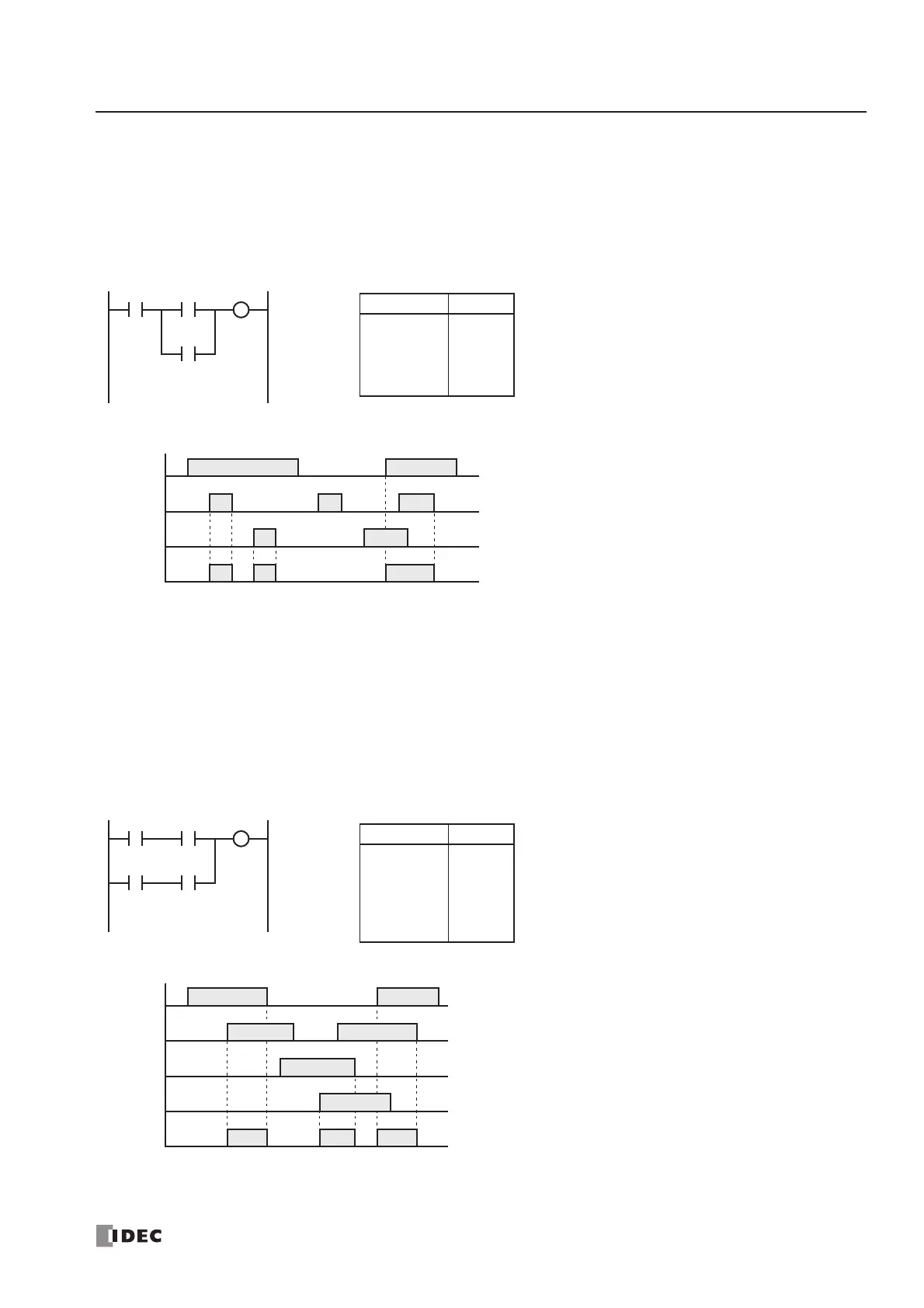
AND LOD (Load)
The AND LOD instruction is used to connect, in series, two or more circuits starting with the LOD instruction. The AND
LOD instruction is the equivalent of a “node” on a ladder diagram.
When using WindLDR, the user need not program the AND LOD instruction. The circuit in the ladder diagram shown
below is converted into AND LOD when the ladder diagram is compiled.
OR LOD (Load)
The OR LOD instruction is used to connect, in parallel, two or more circuits starting with the LOD instruction. The OR
LOD instruction is the equivalent of a “node” on a ladder diagram.
When using WindLDR, the user need not program the OR LOD instruction. The circuit in the ladder diagram shown below
is converted into OR LOD when the ladder diagram is compiled.
Ladder Diagram
I0
I2
I0
ON
OFF
I2
ON
OFF
I3
ON
OFF
Q0
ON
OFF
Timing Chart
When input I0 is on and either input I2 or
I3 is on, output Q0 is on.
When input I0 is off or both inputs I2 and
I3 are off, output Q0 is off.
I3
Instruction Data
LOD
LOD
OR
ANDLOD
OUT
I0
I2
I3
Q0
Program List
Q0
I2
I0
I1
I3
Ladder Diagram
I0
ON
OFF
I1
ON
OFF
I2
ON
OFF
I3
ON
OFF
Timing Chart
When both inputs I0 and I1 are on or both
inputs I2 and I3 are on, output Q0 is on.
When either input I0 or I1 is off and either
input I2 or I3 is off, output Q0 is off.
Q0
ON
OFF
Instruction Data
LOD
AND
LOD
AND
ORLOD
OUT
I0
I1
I2
I3
Q0
Program List
Q0
 Loading...


