7: BASIC INSTRUCTIONS
7-22 « FC4A MICROSMART USER’S MANUAL »
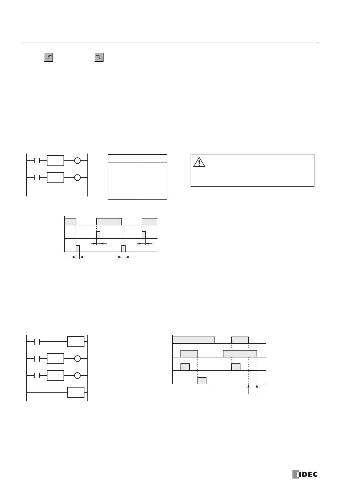
SOTU and SOTD (Single Output Up and Down)
The SOTU instruction “looks for” the transition of a given input from off to on. The SOTD instruction looks for the transi-
tion of a given input from on to off. When this transition occurs, the desired output will turn on for the length of one scan.
The SOTU or SOTD instruction converts an input signal to a “one-shot” pulse signal.
A total of 512 (all-in-one 10-I/O type CPU module) or 3072 (other CPU modules) SOTU and SOTD instructions can be
used in a user program.
If operation is started while the given input is already on, the SOTU output will not turn on. The transition from off to on is
what triggers the SOTU instruction.
When a relay of the CPU or relay output module is defined as the SOTU or SOTD output, it may not operate if the scan
time is not compatible with relay requirements.
There is a special case when the SOTU and SOTD instructions are used between the MCS and MCR instructions (which
are detailed on page 7-23). If input I2 to the SOTU instruction turns on while input I1 to the MCS instruction is on, then
the SOTU output turns on. If input I2 to the SOTD instruction turns off while input I1 is on, then the SOTD output turns
on. If input I1 turns on while input I2 is on, then the SOTU output turns on. However, if input I1 turns off while input I2 is
on, then the SOTD output does not turn on as shown below.
 Loading...


