5: SPECIAL FUNCTIONS
5-20 « FC4A MICROSMART USER’S MANUAL »
Interrupt Input
All MicroSmart CPU modules have an interrupt input function. When a quick response to an external input is required,
such as positioning control, the interrupt input can call a subroutine to execute an interrupt program.
Four inputs I2 through I5 can be designated to execute interrupt at a rising and/or falling edge of input pulses. When an
interrupt is initiated by inputs I2 through I5, program execution immediately jumps to a predetermined label number
stored in special data registers D8032 through D8035, respectively. The Function Area Settings dialog box is used to des-
ignate inputs I2 through I5 as an interrupt input, normal input, high-speed counter input, or catch input.
Normal input signals to input terminals are read when the END instruction is executed at the end of a scan.
Since these settings relate to the user program, the user program must be downloaded to the MicroSmart after changing
any of these settings.
Interrupt Input Terminals, Special Data Registers, and Special Internal Relays for Interrupt Inputs
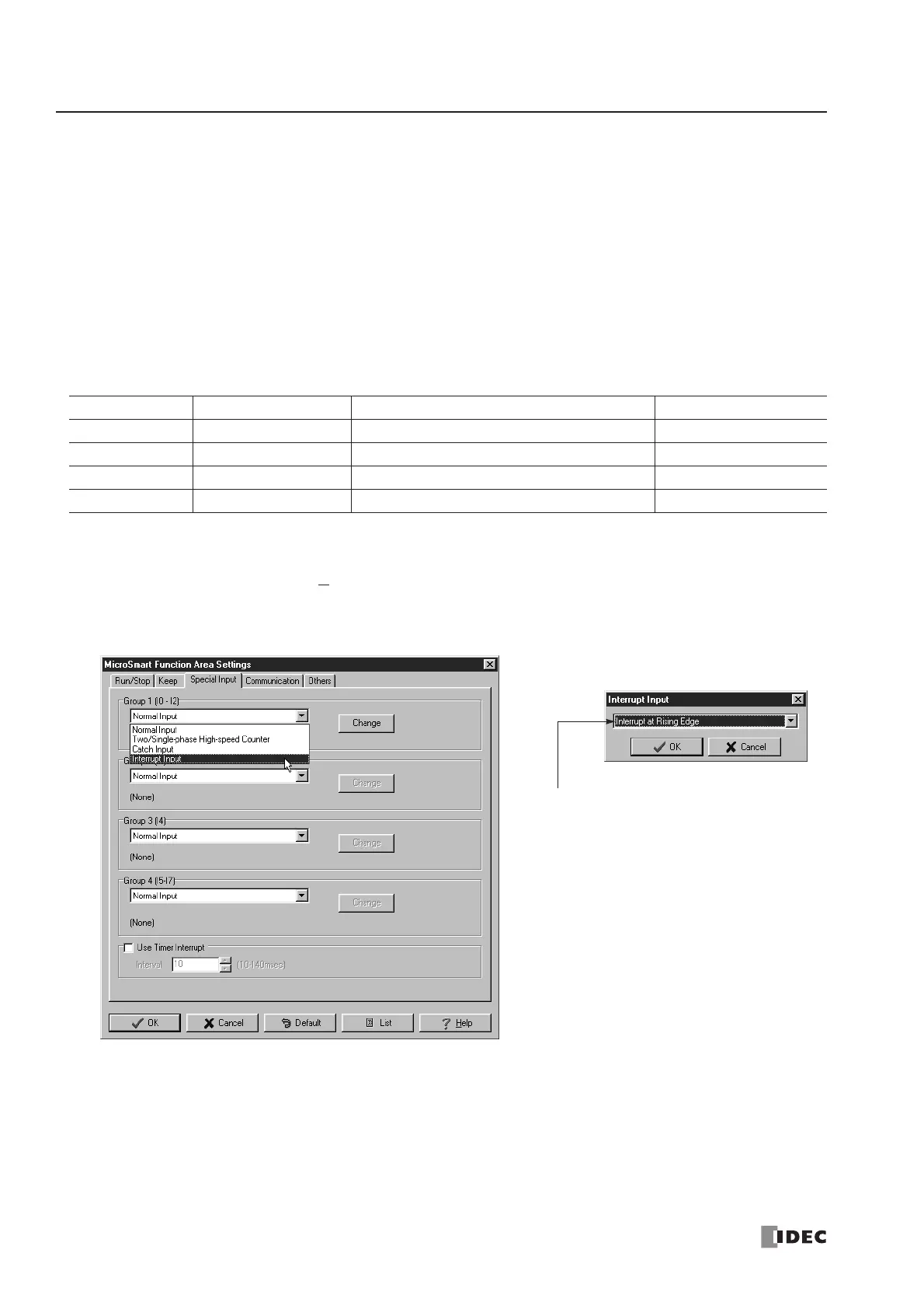
Programming WindLDR
1. From the
WindLDR menu bar, select Configure > Function Area Settings. The Function Area Settings dialog box
appears.
2. Select the Special Input tab.
3. Select Interrupt Input in the Groups 1 through 4 pull-down list boxes. the Interrupt Input dialog box appears.
4. Select an interrupt edge in the pull-down list for each group.
Disable and Enable Interrupts
The interrupt inputs I2 through I5 and timer interrupt are normally enabled while the CPU is running, and can also be indi-
vidually disabled using the DI instruction or enabled using the EI instruction. When interrupt inputs I2 through I5 are
enabled, special internal relay M8140 through M8143 are turned on, respectively. See page 18-7.
Group Interrupt Input No. Interrupt Input Jump Destination Label No. Interrupt Input Status
Group 1 I2 D8032 M8140
Group 2 I3 D8033 M8141
Group 3 I4 D8034 M8142
Group 4 I5 D8035 M8143
Interrupt Input Rising/Falling Edge Selection
Interrupt at Rising Edge
Interrupt occurs when the interrupt input
turns on.
Interrupt at Falling Edge
Interrupt occurs when the interrupt input
turns off.
Interrupt at Both Edges
Interrupt occurs when the interrupt input
turns on or off.
 Loading...


