« FC4A MICROSMART USER’S MANUAL » 7-1
7: BASIC INSTRUCTIONS
Introduction
This chapter describes programming of the basic instructions, available operands, and sample programs.
All basic instructions are available on all MicroSmart CPU modules.
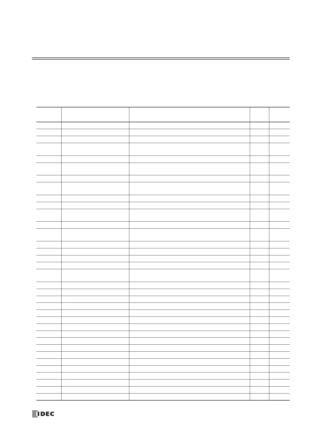
Basic Instruction List
Symbol Name Function
Qty of
Bytes
See
Page
AND And Series connection of NO contact 4 7-4
AND LOD And Load Series connection of circuit blocks 5 7-5
ANDN And Not Series connection of NC contact 4 7-4
BPP Bit Pop
Restores the result of bit logical operation which was
saved temporarily
2 7-6
BPS Bit Push Saves the result of bit logical operation temporarily 5 7-6
BRD Bit Read
Reads the result of bit logical operation which was
saved temporarily
3 7-6
CC= Counter Comparison (=) Equal to comparison of counter current value 7 7-14
CC≥ Counter Comparison (≥)
Greater than or equal to comparison of counter current
value
7 7-14
CDP Dual Pulse Reversible Counter Dual pulse reversible counter (0 to 65535) 4 7-10
CNT Adding Counter Adding counter (0 to 65535) 4 7-10
CUD
Up/Down Selection
Reversible Counter
Up/down selection reversible counter (0 to 65535) 4 7-10
DC= Data Register Comparison (=) Equal to comparison of data register value 8 7-16
DC≥ Data Register Comparison (≥)
Greater than or equal to comparison of data register
value
8 7-16
END End Ends a program 2 7-26
JEND Jump End Ends a jump instruction 4 7-25
JMP Jump Jumps a designated program area 4 7-25
LOD Load Stores intermediate results and reads contact status 6 7-2
LODN Load Not
Stores intermediate results and reads inverted contact
status
6 7-2
MCR Master Control Reset Ends a master control 4 7-23
MCS Master Control Set Starts a master control 4 7-23
OR Or Parallel connection of NO contact 4 7-4
OR LOD Or Load Parallel connection of circuit blocks 5 7-5
ORN Or Not Parallel connection of NC contact 4 7-4
OUT Output Outputs the result of bit logical operation 6 7-2
OUTN Output Not Outputs the inverted result of bit logical operation 6 7-2
RST Reset Resets output, internal relay, or shift register bit 6 7-3
SET Set Sets output, internal relay, or shift register bit 6 7-3
SFR Shift Register Forward shift register 6 7-18
SFRN Shift Register Not Reverse shift register 6 7-18
SOTD Single Output Down Falling-edge differentiation output 5 7-22
SOTU Single Output Up Rising-edge differentiation output 5 7-22
TIM 100-ms Timer Subtracting 100-ms timer (0 to 6553.5 sec) 4 7-7
TMH 10-ms Timer Subtracting 10-ms timer (0 to 655.35 sec) 4 7-7
TML 1-sec Timer Subtracting 1-sec timer (0 to 65535 sec) 4 7-7
TMS 1-ms Timer Subtracting 1-ms timer (0 to 65.535 sec) 4 7-7
 Loading...


