14: DATA CONVERSION INSTRUCTIONS
14-2 « FC4A MICROSMART USER’S MANUAL »
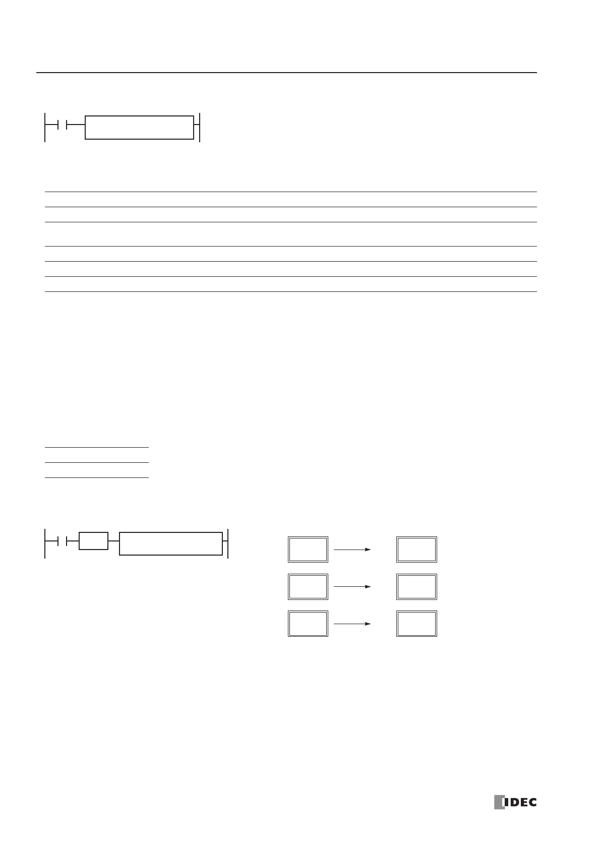
BTOH (BCD to Hex)
Applicable CPU Modules
Valid Operands
For the valid operand number range, see pages 6-1 and 6-2.
▲ Internal relays M0 through M1277 can be designated as D1. Special internal relays cannot be designated as D1.
When T (timer) or C (counter) is used as S1, the timer/counter current value is read out. When T (timer) or C (counter) is
used as D1, the data is written in as a preset value which can be 0 through 65535.
Valid values for the source operand are 0 through 9999 (BCD). Make sure that each digit of the source designated by S1 is
0 through 9. If the source data is out of the valid range, a user program execution error will result, turning on special inter-
nal relay M8004 and the ERR LED.
Since the BTOH instruction is executed in each scan while input is on, a pulse input from a SOTU or SOTD instruction
should be used as required.
Valid Data Types
Example: BTOH
FC4A-C10R2/C FC4A-C16R2/C FC4A-C24R2/C FC4A-D20K3/S3 FC4A-D20RK1/RS1 & FC4A-D40K3/S3
XXX X X
Operand Function I Q M R T C D Constant Repeat
S1 (Source 1) BCD data to convert XXXXXXX X —
D1 (Destination 1) Destination to store conversion results — X ▲ XXXX — —
W (word) I (integer)
X—
S1 → D1
When input is on, the BCD data designated by S1 is converted into 16-bit binary
data and stored to the destination designated by operand D1.
Valid values for the source operand are 0 through 9999 (BCD).
BTOH(W) S1
*****
D1
*****
When a bit operand such as I (input), Q (output), M (internal relay), or R (shift register) is
designated as the source or destination, 16 points are used.
When a word operand such as T (timer), C (counter), or D (data register) is designated as the
source or destination, 1 point is used.
D1
D20
S1
D10
I1
BTOH(W)
BCD
SOTU
0
D10
(0000h)
Binary
0
D20
(0000h)
4660
D10
(1234h)
1234
D20
(04D2h)
39321
D10
(9999h)
9999
D20
(270Fh)
 Loading...


