9: MOVE INSTRUCTIONS
9-2 « FC4A MICROSMART USER’S MANUAL »
Examples: MOV
The following examples are described using the word data type. Data move operation for the integer data type is the same
for the word data type.
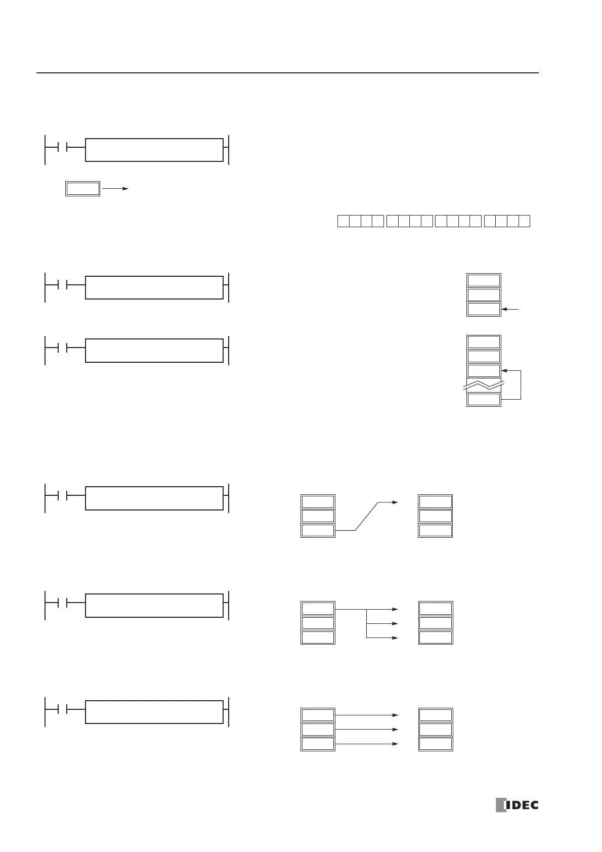
Repeat Operation in the Move Instructions
Repeat Source Operand
When the S1 (source) is designated with repeat, operands as many as the repeat cycles starting with the operand designated
by S1 are moved to the destination. As a result, only the last of the source operands is moved to the destination.
Repeat Destination Operand
When the D1 (destination) is designated to repeat, the source operand designated by S1 is moved to all destination oper-
ands as many as the repeat cycles starting with the destination designated by D1.
Repeat Source and Destination Operands
When both S1 (source) and D1 (destination) are designated to repeat, operands as many as the repeat cycles starting with
the operand designated by S1 are moved to the same quantity of operands starting with the operand designated by D1.
I2
REP
D10 → M0
When input I2 is on, the data in data register D10 designated by source
operand S1 is moved to 16 internal relays starting with M0 designated by
destination operand D1.
12345
D10
S1 –
D10
D1 –
M0
M0 through M7, M10 through M17
The data in the source data register is converted into 16-bit binary
data, and the ON/OFF statuses of the 16 bits are moved to internal
relays M0 through M7 and M10 through M17. M0 is the LSB (least
significant bit). M17 is the MSB (most significant bit).
MOV(W)
0 1 0010 0 0 0 1 0010 1 1
MSB
M0
LSB
M17 M7M10
I0
REP
810 → D2
When input I0 is on, constant 810 designated
by source operand S1 is moved to data register
D2 designated by destination operand D1.
D1
D0
810
D2
810
S1 –
810
D1 –
D2
MOV(W)
I1
REP
D10 → D2
When input I1 is on, the data in data register
D10 designated by source operand S1 is moved
to data register D2 designated by destination
operand D1.
D1
D0
930
D2
930
D10
S1 –
D10
D1 –
D2
MOV(W)
111
D11
110
D10
112
D12
D21
112
D20
D22
Source (Repeat = 3) Destination (Repeat = 0)
I1
REP
3
S1 R
D10
D1 –
D20
MOV(W)
111
D11
110
D10
112
D12
110
D21
110
D20
110
D22
Source (Repeat = 0) Destination (Repeat = 3)
I3
REP
3
S1 –
D10
D1 R
D20
MOV(W)
111
D11
110
D10
112
D12
111
D21
110
D20
112
D22
Source (Repeat = 3) Destination (Repeat = 3)
I5
REP
3
S1 R
D10
D1 R
D20
MOV(W)
 Loading...


