18: PROGRAM BRANCHING INSTRUCTIONS
« FC4A MICROSMART USER’S MANUAL » 18-7
DI (Disable Interrupt)
EI (Enable Interrupt)
Applicable CPU Modules
Valid Operands
Interrupt inputs I2 through I5 and timer interrupt selected in the Function Area Settings are normally enabled when the
CPU starts. When the DI instruction is executed, interrupt inputs and timer interrupt designated as source operand S1 are
disabled even if the interrupt condition is met in the user program area subsequent to the DI instruction. When the EI
instruction is executed, disabled interrupt inputs and timer interrupt designated as source operand S1 are enabled again in
the user program area subsequent to the EI instruction. Different operands can be selected for the DI and EI instructions to
disable and enable interrupt inputs selectively. For Interrupt Input and Timer Interrupt, see pages 5-20 and 5-22.
Make sure that interrupt inputs and timer interrupt designated as source operand S1 are selected in the Function Area Set-
tings. Otherwise, when the DI or EI instruction is executed, a user program execution error will result, turning on special
internal relay M8004 and the ERR LED on the CPU module.
The DI and EI instructions cannot be used in an interrupt program. If used, a user program execution error will result, turn-
ing on special internal relay M8004 and the ERR LED on the CPU module.
Special Internal Relays M8140-M8144: Interrupt Status
Special internal relays M8140 through M8144 are provided to indicate whether interrupt inputs and timer interrupt are
enabled or disabled.
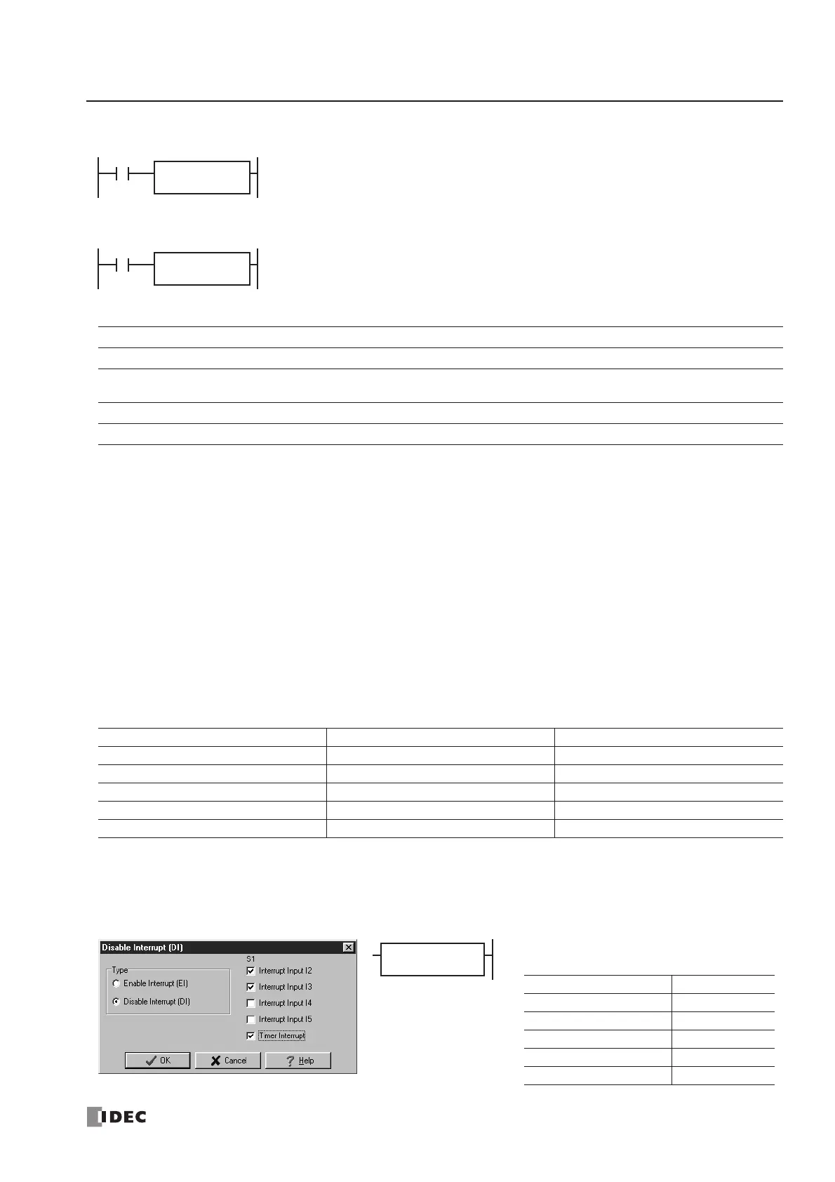
Programming WindLDR
In the Disable Interrupt (DI) or Enable Interrupt (EI) dialog box, click the check box on the left of Interrupt Inputs I2
through I5 or Timer Interrupt to select source operand S1. The example below selects interrupt inputs I2, I3, and timer
interrupt for the DI instruction, and a 19 will be shown as source operand S1.
FC4A-C10R2/C FC4A-C16R2/C FC4A-C24R2/C FC4A-D20K3/S3 FC4A-D20RK1/RS1 & FC4A-D40K3/S3
——— — X
Operand Function I Q M R T C D Constant Repeat
S1 (Source 1) Interrupt inputs and timer interrupt ——————— 1-31 —
Interrupt Interrupt Enabled Interrupt Disabled
Interrupt Input I2 M8140 ON M8140 OFF
Interrupt Input I3 M8141 ON M8141 OFF
Interrupt Input I4 M8142 ON M8142 OFF
Interrupt Input I5 M8143 ON M8143 OFF
Timer Interrupt M8144 ON M8144 OFF
are disabled.
are enabled.
 Loading...


