2: MODULE SPECIFICATIONS
« FC4A MICROSMART USER’S MANUAL » 2-39
Mixed I/O Modules
The 4-in/4-out mixed I/O module has 4-point DC sink/source inputs and 4-point relay outputs, with a screw terminal block
for I/O wiring. The 16-in/8-out mixed I/O module has 16-point DC sink/source inputs and 8-point relay outputs, with a
wire-clamp terminal block for I/O wiring.
The mixed I/O modules can be connected to the all-in-one 24-I/O type CPU module and all slim type CPU modules to
expand input and output terminals. The all-in-one 10- and 16-I/O type CPU modules cannot connect mixed I/O modules.
Mixed I/O Module Type Numbers
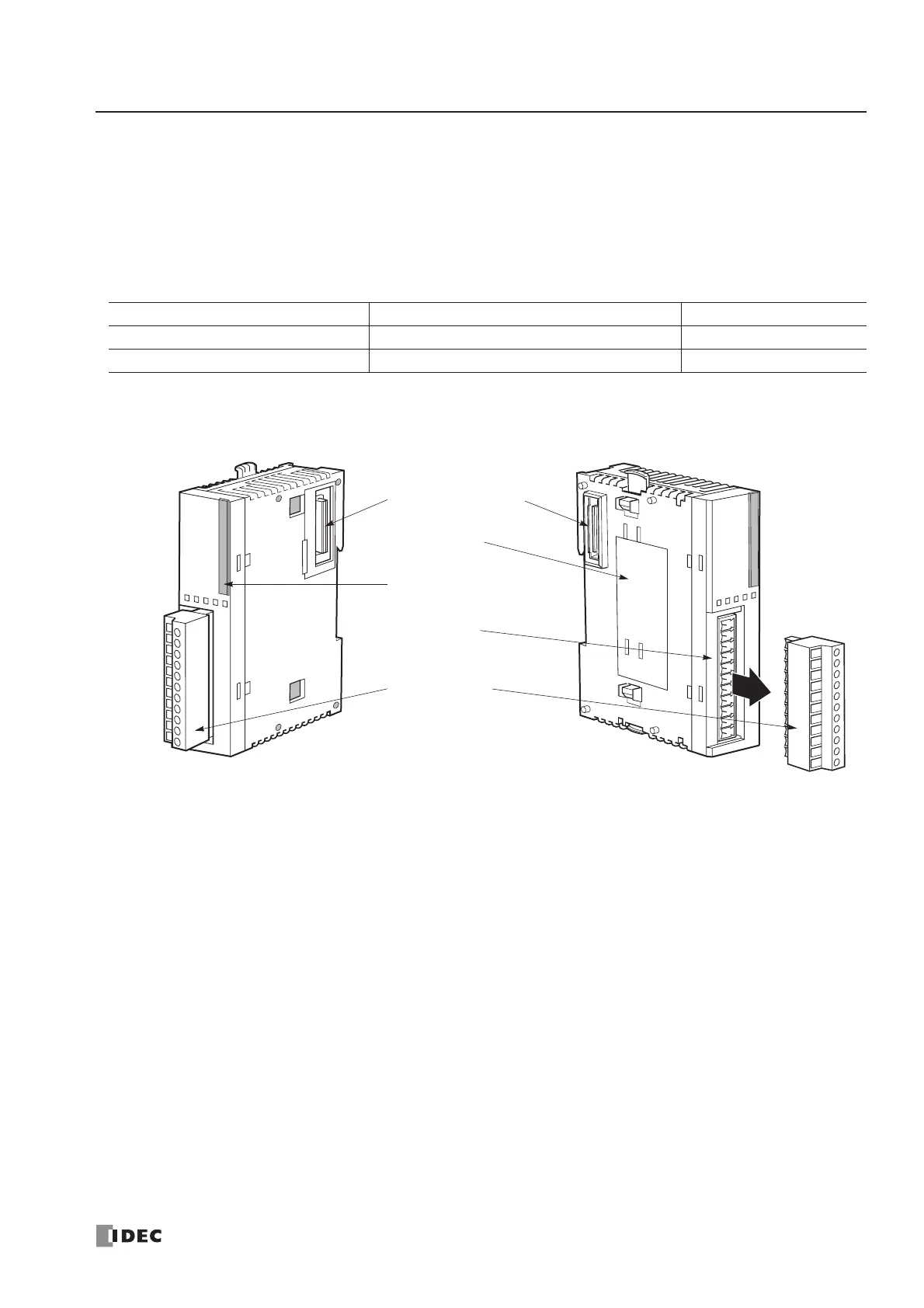
Parts Description
(1) Expansion Connector Connects to the CPU and other I/O modules.
(The all-in-one 10- and 16-I/O type CPU modules cannot be connected.)
(2) Module Label Indicates the mixed I/O module Type No. and specifications.
(3) LED Indicator Turns on when a corresponding input or output is on.
(4) Terminal No. Indicates terminal numbers.
(5) Cable Terminal Two different terminal styles are available for wiring.
Module Name Terminal Type No.
4-in/4-out Mixed I/O Module Removable Terminal Block FC4A-M08BR1
16-in/8-out Mixed I/O Module Non-removable Wire-clamp Terminal Block FC4A-M24BR2
 Loading...


