28: AS-INTERFACE MASTER COMMUNICATION
28-6 « FC4A MICROSMART USER’S MANUAL »
Operation Basics
This section describes simple operating procedures for the basic AS-Interface system from programming WindLDR on a
computer to monitoring the slave operation.
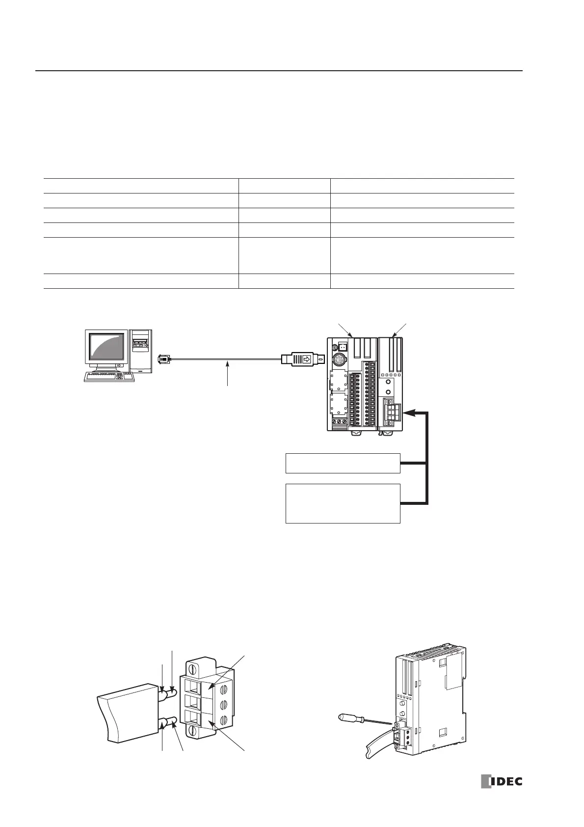
AS-Interface System Setup
The sample AS-Interface system consists of the following devices:
AS-Interface Cable Wiring
Before wiring the AS-Interface cable, remove the AS-Interface cable terminal block from the AS-Interface cable connector
on the AS-Interface master module.
AS-Interface specifies use of brown cables for the AS-Interface + line, and blue cables for the AS-Interface – line. Connect
the cables to match the color labels on the terminal block. Tighten the terminal screws to a torque of 0.5 to 0.6 N·m.
Insert the terminal block to the connector on the AS-Interface master module, and tighten the mounting screws to a torque
of 0.3 to 0.5 N·m.
Name Type No. Description
FC4A MicroSmart Slim Type CPU Module FC4A-D20RK1 —
MicroSmart AS-Interface Master Module FC4A-AS62M —
WindLDR FC9Y-LP2CDW Version 5.0 or higher
AS-Interface Standard Slave —
1 unit
Address 0
ID: 0, I/O: 7, ID2: F, ID1: 7
AS-Interface Power Supply PS2R-Q30ABL Output 30.5V DC, 2.4A (73W)
Slim Type CPU Module
FC4A-D20RK1
AS-Interface Master Module
FC4A-AS62M
Standard
AS-Interface Cable
Computer Link Cable 4C
FC2A-KC4C
3m (9.84 ft.) long
AS-Interface Power Supply
Standard Slave
Address 0
ID: 0, I/O: 7, ID2: F, ID1: 7
 Loading...


