28: AS-INTERFACE MASTER COMMUNICATION
« FC4A MICROSMART USER’S MANUAL » 28-35
SwitchNet Data I/O Port
SwitchNet control units can be used as slaves in the AS-Interface network and are available in ø16mm L6 series and
ø22mm HW series. Input signals to the MicroSmart AS-Interface master module are read to internal relays allocated to
each input point designated by a slave number and a DI number. Similarly, output signals from the MicroSmart AS-Inter-
face master module are written to internal relays allocated to each output point designated by a slave number and a DO
number. When programming a ladder diagram for the MicroSmart, use internal relays allocated to input signals and output
signals of SwitchNet control units.
L6 series and HW series SwitchNet control units have slightly different digital I/O data allocations.
L6 Series Digital I/O Data Allocation
Input data is sent from slaves to the AS-Interface master. Output data is sent from the AS-Interface master to slaves.
Notes:
SwitchNet L6 Series
Slave Unit
Used I/O
Input Data
(slave send data)
Output Data
(slave receive data)
DI3 DI2 DI1 DI0 DO3 DO2 DO1 DO0
Pushbutton 1 in 0 X1 1 1 * — — —
Pilot light 1 out 0 0 1 1 * — — X1
Illuminated pushbutton 1 in/1 out 0 X1 1 1 * — — X1
Selector, Key selector, Lever: 2-position 1 in 0 X2 1 1 * — — —
Selector, Key selector, Lever: 3-position 2 in X3 X3 1 1 * — — —
Illuminated selector: 2-position 1 in/1 out 0 X2 1 1 * — — X1
Illuminated selector: 3-position 2 in/1 out X3 X3 1 1 * — — X1
1. ∗ The AS-Interface master uses bit DO3 for addressing A/B
slaves.
2. In the above table, bits marked with X1, X2, and X3 are used
for SwitchNet I/O data.
3. X1: When pushbutton is pressed, input data is 1 (on). When
not pressed, input data is 0 (off). When output data is 1 (on),
LED is on. When output data is 0 (off), LED is off.
4. X2: The input data from 2-position selector, key selector, and
illuminated selector switches and 2-position lever switches
depend on the operator position as shown below.
5. X3: The input data from 3-position selector, key selector, and
illuminated selector switches and 3-position lever switches
depend on the operator position as shown below.
6. Unused input bits DI3 and DI2 are 0 (off), and unused input
bits DI1 and DI0 are 1 (on). Slaves ignore unused output data
(—) sent from the master.
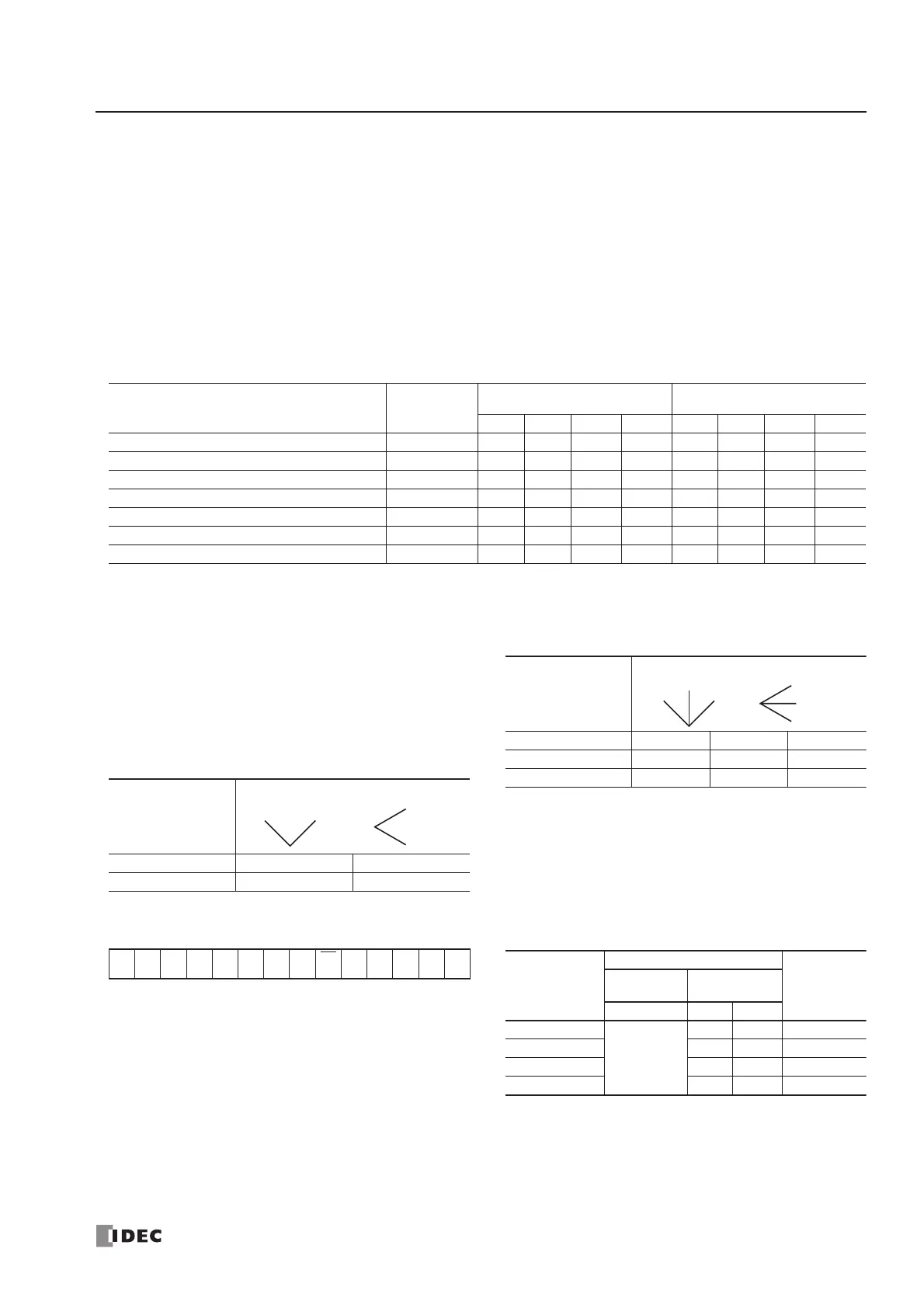
2-position Operator
Operator Position Left/Down Right/Up
DI2 0 1
Selector
Left
Right
Up
Down
Lever
3-position Operator
Operator Position Left/Down Center Right/Up
DI3 0 0 1
DI2 1 0 0
Selector
Left
Right
Center
Up
Center
Down
Lever
• Write_Parameter Command • Write_Parameter Settings
00A4A3 A2 A1 A0 1
Sel
P3
P2 P1 P0 PB 1
LED
Brightness
Settings
Remarks
Output
Selection
Control Data
P2 P1 P0
100%
1: DO0
0: DO1
11 Default
50% 0 1
25% 1 0
12.5% 0 0