5: SPECIAL FUNCTIONS
5-30 « FC4A MICROSMART USER’S MANUAL »
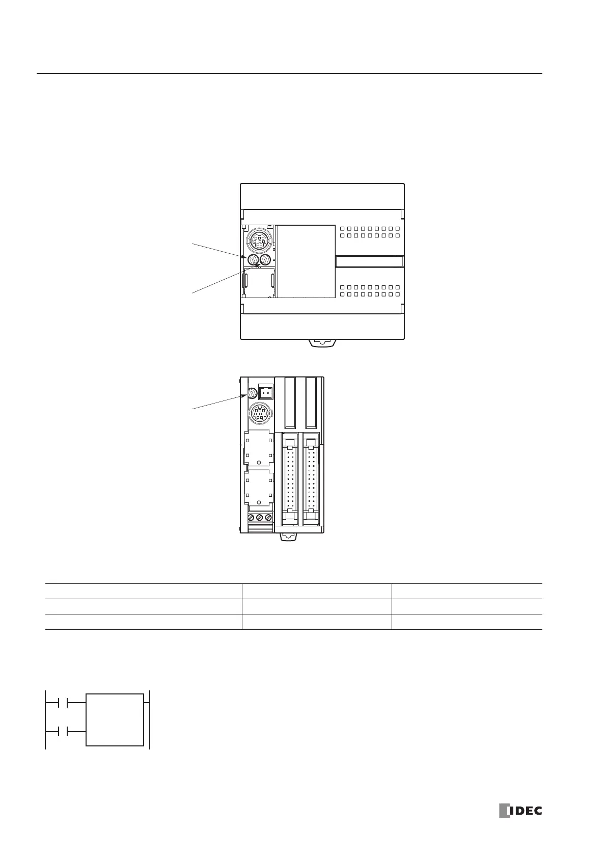
Analog Potentiometers
The all-in-one 10- and 16-I/O type CPU modules and every slim type CPU module have one analog potentiometer. Only
the 24-I/O type CPU module has two analog potentiometers. The values (0 through 255) set with analog potentiometers 1
and 2 are stored to data registers D8057 and D8058, respectively, and updated in every scan.
The analog potentiometer can be used to change the preset value for a timer or counter.
Special Data Registers for Analog Potentiometers
Example: Changing Counter Preset Value Using Analog Potentiometer
This example demonstrates a program to change a counter preset value using analog potentiometer 1.
CPU Module Analog Potentiometer 1 Analog Potentiometer 2
FC4A-C24R2 and FC4A-C24R2C D8057 D8058
Other CPU Modules D8057 —
value for counter C0.
 Loading...


