7: BASIC INSTRUCTIONS
7-14 « FC4A MICROSMART USER’S MANUAL »
CC= and CC≥ (Counter Comparison)
The CC= instruction is an equivalent comparison instruction for counter current values. This instruction will constantly
compare current values to the value that has been programmed in. When the counter value equals the given value, the
desired output will be initiated.
The CC≥ instruction is an equal to or greater than comparison instruction for counter current values. This instruction will
constantly compare current values to the value that has been programmed in. When the counter value is equal to or greater
than the given value, the desired output will be initiated.
When a counter comparison instruction is programmed, two addresses are required. The circuit for a counter comparison
instruction must be programmed in the following order: the CC= or CC≥ instruction; a counter number C0 through C31
(all-in-one 10-I/O type CPU module) or C99 (other CPU modules); followed by a preset value to compare from 0 to
65535.
The preset value can be designated using a decimal constant or a data register D0 through D399 (all-in-one 10-I/O type
CPU module) or D1299 (other CPU modules), or D2000 through D7999 (slim type CPU modules). When a data register is
used, the data of the data register becomes the preset value.
• The CC= and CC≥ instructions can be used repeatedly for different preset values.
• The comparison instructions only compare the current value. The status of the counter does not affect this function.
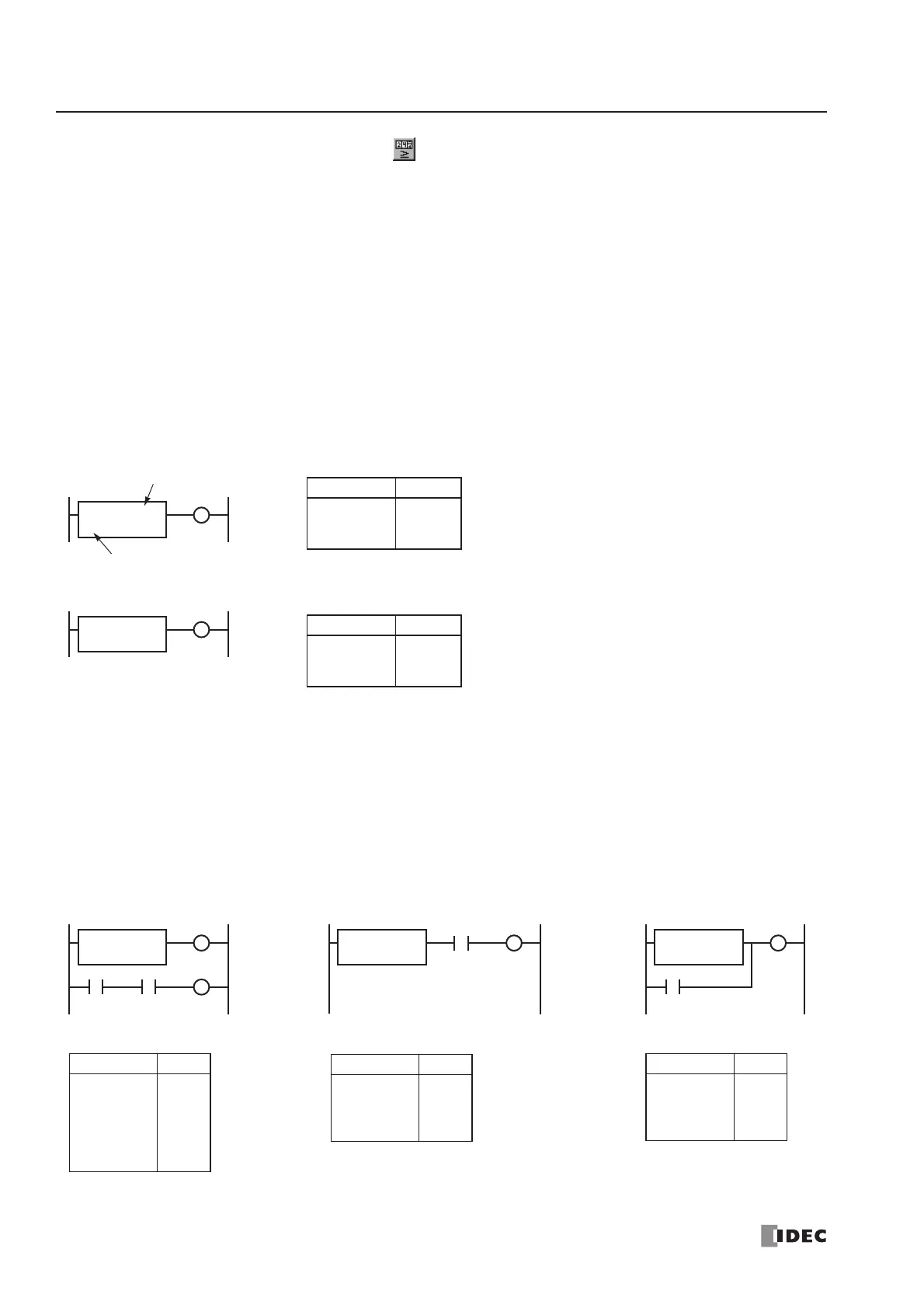
• The comparison instructions also serve as an implicit LOD instruction, and must be programmed at the beginning of a
ladder line.
• The comparison instructions can be used with internal relays, which are ANDed or ORed at a separate program
address.
• Like the LOD instruction, the comparison instructions can be followed by the AND and OR instructions.
 Loading...


