6: ALLOCATION NUMBERS
6-18 « FC4A MICROSMART USER’S MANUAL »
Expansion I/O Module Operands
Expansion I/O modules are available in digital I/O modules and analog I/O modules.
Among the all-in-one type CPU modules, only the 24-I/O type CPU modules (FC4A-C24R2 and FC4A-C24R2C) can
connect a maximum of four expansion I/O modules including analog I/O modules.
All slim type CPU modules can connect a maximum of seven expansion I/O modules including analog I/O modules.
I/O Expansion for All-in-One Type CPU Modules
A maximum of four input, output, mixed I/O, or analog I/O modules can be mounted with the 24-I/O type CPU module, so
that the I/O points can be expanded to a maximum of 78 inputs or 74 outputs. The total of inputs and outputs can be a max-
imum of 88 points. Input and output numbers are automatically allocated to each digital I/O module, starting with I30 and
Q30, in the order of increasing distance from the CPU module. Expansion I/O modules cannot be mounted with the 10-
and 16-I/O type CPU modules (FC4A-C10R2, FC4A-C10R2C, FC4A-C16R2, and FC4A-C16R2C).
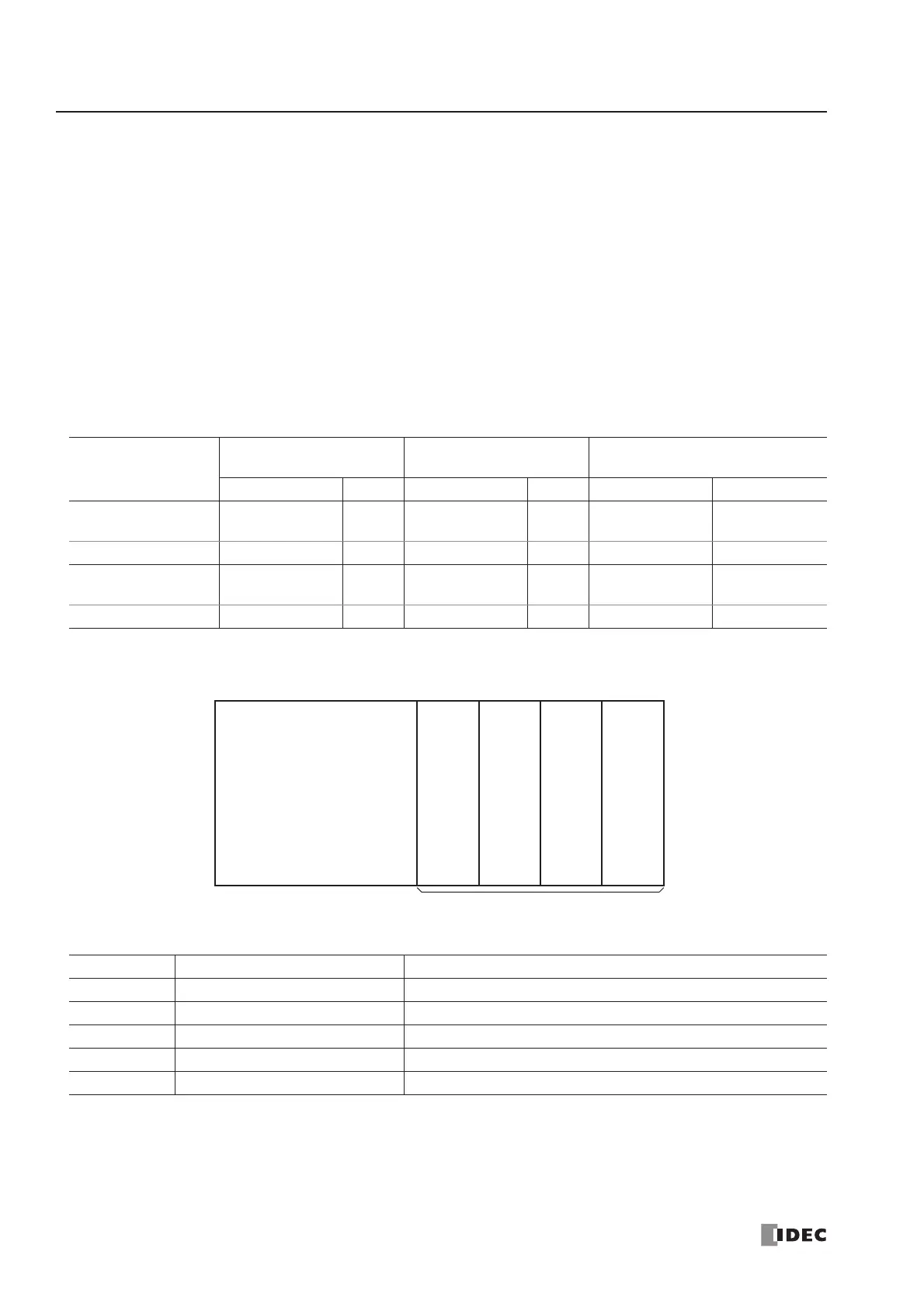
I/O Allocation Numbers (All-in-One Type CPU Modules)
Example:
The system setup shown above will have I/O operand numbers allocated for each module as follows:
The I/O numbers of the CPU module start with I0 and Q0. The I/O numbers of the expansion I/O modules start with I30
and Q30. The mixed I/O module has 4 inputs and 4 outputs. When an I/O module is mounted next to a mixed I/O module,
note that the allocation numbers skip four points as shown above.
Input and output modules may be grouped together for easy identification of I/O numbers. When the I/O modules are relo-
cated, the I/O numbers are renumbered automatically.
Operand
FC4A-C10R2
FC4A-C10R2C
FC4A-C16R2
FC4A-C16R2C
FC4A-C24R2
FC4A-C24R2C
Allocation No. Points Allocation No. Points Allocation No. Points
Input (I) I0 - I5 6
I0 - I7
I10
9
I0 - I7
I10 - I15
14
Expansion Input (I) — — — — I30 - I107 64 (78 total)
Output (Q) Q0 - Q3 4 Q0 - Q6 7
Q0 - Q7
Q10 - Q11
10
Expansion Output (Q) — — — — Q30 - Q107 64 (74 total)
Slot No. Module I/O Operand Numbers
24-I/O Type CPU Module I0 to I7, I10 to I15, Q0 to Q7, Q10 and Q11
1 16-pt Input Module I30 to I37, I40 to I47
2 Analog I/O Module See page 24-8.
3 4/4-pt Mixed I/O Module I50 to I53, Q30 to Q33
4 8-pt Input Module I60 to I67
 Loading...


