« FC4A MICROSMART USER’S MANUAL » 27-1
27: MODEM MODE
Introduction
This chapter describes the modem mode designed for communication between the MicroSmart and another MicroSmart or
any data terminal equipment through telephone lines. Using the modem mode, the MicroSmart can initialize a modem,
dial a telephone number, send an AT command, enable the answer mode to wait for an incoming call, and disconnect the
telephone line. These operations can be performed simply by turning on a start internal relay dedicated to each operation.
System Setup
To connect a modem to the MicroSmart, install the RS232C communication adapter (FC4A-PC1) to the port 2 connector
on the all-in-one 16- or 24-I/O type CPU module, or mount the RS232C communication module (FC4A-HPC1) next to the
slim type CPU module, and use the modem cable 1C (FC2A-KM1C). To enable the modem mode, select Modem Protocol
for Port 2 using WindLDR (Configure > Function Area Settings > Communication). The all-in-one 10-I/O type CPU
module does not have the modem communication capability.
Caution
• The modem mode provides for a simple modem control function so that the MicroSmart can ini-
tialize a modem, dial a destination telephone number, or answer an incoming call. The perfor-
mance of the modem communication using the modem mode depends on the modem functions
and telephone line situations. The modem mode does not prevent intrusion or malfunctions of
other systems. For practical applications, confirm the communication function using the actual
system setup and include safety provisions.
• While communicating through modems, the telephone line may be disconnected unexpectedly or
receive data errors may occur. Provisions against such errors must be included in the user program.
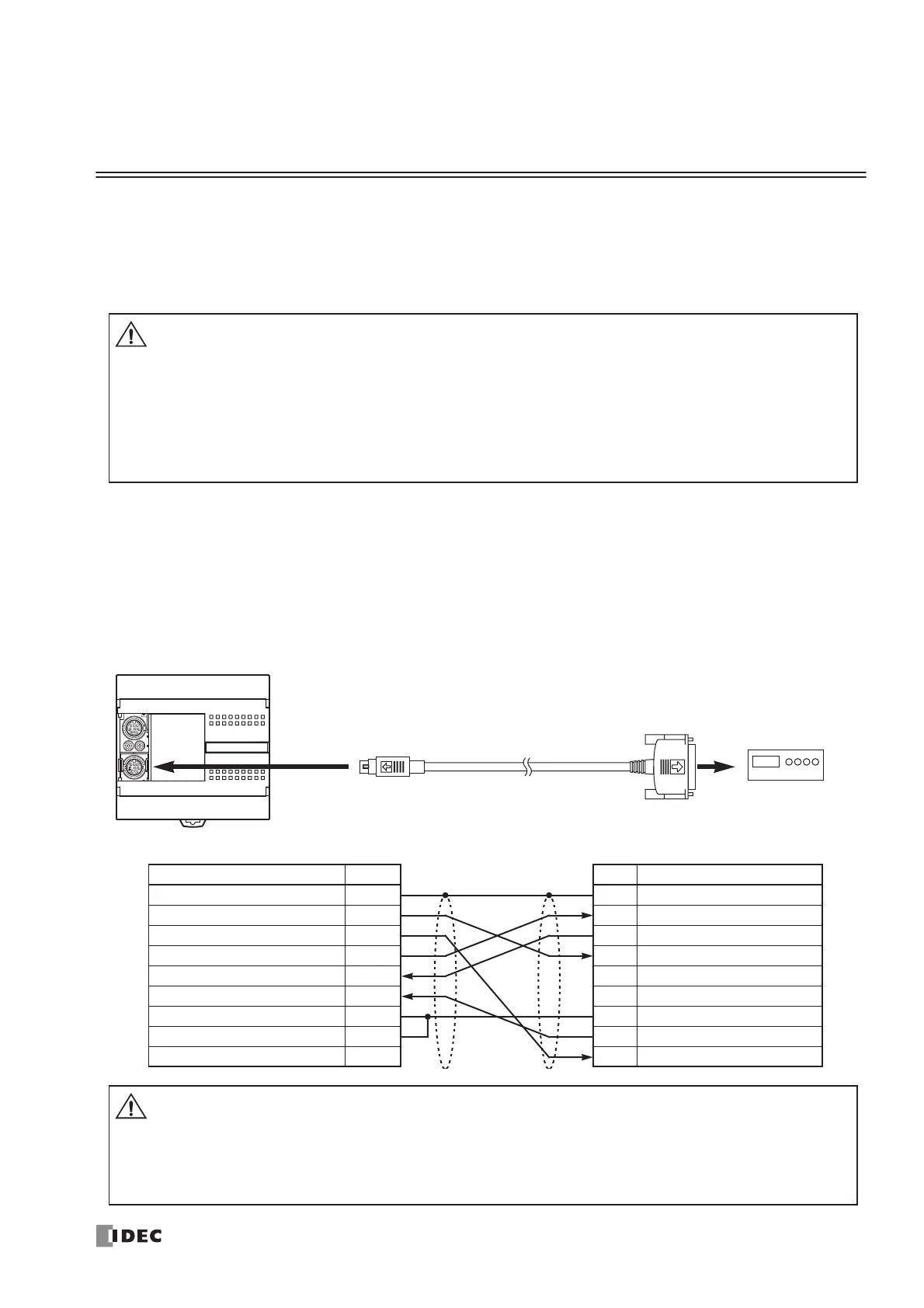
Modem Cable 1C
FC2A-KM1C
3m (9.84 ft.) long
To RS232C Port
D-sub 25-pin
Male Connector
D-sub 25-pin Connector Pinouts
Pin Description
1 FG Frame Ground
2 TXD Transmit Data
3 RXD Receive Data
4 RTS Request to Send
5 NC No Connection
6 NC No Connection
7 SG Signal Ground
8 DCD Data Carrier Detect
20 DTR Data Terminal Ready
Modem
Mini DIN Connector Pinouts
Description Pin
Shield Cover
RTS Request to Send 1
DTR Data Terminal Ready 2
TXD Transmit Data 3
RXD Receive Data 4
DSR Data Set Ready 5
SG Signal Ground 6
SG Signal Ground 7
NC No Connection 8
Caution
• Do not connect the NC (no connection) pin to any line; otherwise, the MicroSmart or modem may
be damaged.
• Modem cables for Apple Macintosh computers cannot be used for the MicroSmart.
• Do not connect the cable to the port 1 or port 2 (RS485); otherwise, the MicroSmart or modem
may be damaged.
To Port 2
RS232C Communication Adapter
FC4A-PC1
16- or 24-I/O Type CPU Module
 Loading...


