25: DATA LINK COMMUNICATION
25-2 « FC4A MICROSMART USER’S MANUAL »
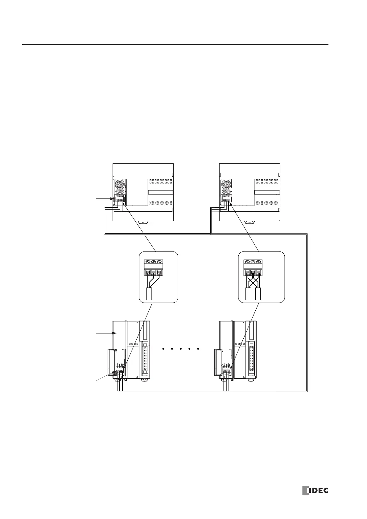
Data Link System Setup
To set up a data link system, install the RS485 communication adapter (FC4A-PC3) to the port 2 connector on the all-in-
one 16- or 24-I/O type CPU module.
When using the slim type CPU module, mount the RS485 communication module (FC4A-HPC3) next to the CPU module.
When using the optional HMI module with the slim type CPU module (not shown below), install the RS485 communica-
tion adapter (FC4A-PC3) to the port 2 connector on the HMI base module.
Connect the RS485 terminals A, B, and SG on every CPU module using a shielded twisted pair cable as shown below. The
total length of the cable for the data link system can be extended up to 200 meters (656 feet).
A B SG
Cable Cable
A B SG
Master Station Slave Station 1
Slave Station 2Slave Station 31
RS485 Communication
Adapter FC4A-PC3
on Port 2 Connector
RS485 Communication
Module FC4A-HPC3
Port 2
All-in-One Type
CPU Module
Slim Type
CPU Module
Shielded twisted pair cable 200 meters (656 feet) maximum
Core wire 0.3mm
2
 Loading...


