14: DATA CONVERSION INSTRUCTIONS
14-14 « FC4A MICROSMART USER’S MANUAL »
ALT (Alternate Output)
Applicable CPU Modules
Valid Operands
For the valid operand number range, see pages 6-1 and 6-2.
Since the ALT instruction is executed in each scan while input is on, a pulse input from a SOTU or SOTD instruction must
be used.
Example: ALT
FC4A-C10R2/C FC4A-C16R2/C FC4A-C24R2/C FC4A-D20K3/S3 FC4A-D20RK1/RS1 & FC4A-D40K3/S3
——— — X
Operand Function I Q M R T C D Constant Repeat
D1 (Destination 1) Bit to turn on and off — X X X — — — — —
When input is turned on, output, internal relay, or shift register bit designated by
D1 is turned on and remains on after the input is turned off.
When input is turned on again, the designated output, internal relay, or shift reg-
ister bit is turned off.
The ALT instruction must be used with a SOTU or SOTD instruction, otherwise the
designated output, internal relay, or shift register bit repeats to turn on and off in
each scan.
ALT D1
*****
SOTU
D1
Q0
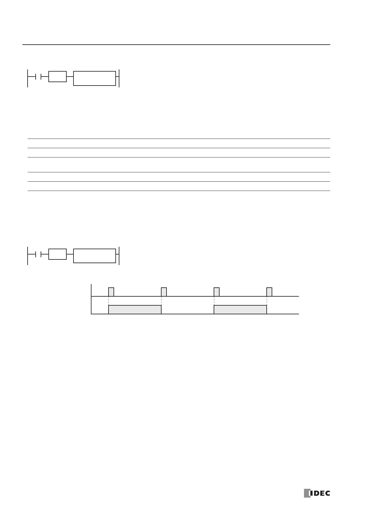
I0
ALT
When input I0 is turned on, output Q0 designated by operand D1 is turned on and
remains after input I0 is turned off.
When input I0 is turned on again, output Q0 is turned off.
SOTU
Input I0
Output Q0
ON
OFF
ON
OFF
 Loading...


