« FC4A MICROSMART USER’S MANUAL » 24-1
24: ANALOG I/O CONTROL
Introduction
The MicroSmart provides analog I/O control capabilities of 12- through 16-bit resolution using analog I/O modules.
This chapter describes the system setup for using analog I/O modules, WindLDR programming procedures, data register
allocation numbers for analog I/O modules, and application examples.
For specifications of analog I/O modules, see page 2-43.
Applicable CPU Modules
END refresh type analog I/O modules as many as listed below can be used with any FC4A MicroSmart CPU module sys-
tem program versions.
Ladder refresh type analog I/O modules can be used with the FC4A MicroSmart CPU module system program versions as
listed below.
All-in-one 10- and 16-I/O type CPU modules cannot use either END refresh or ladder refresh type analog I/O modules.
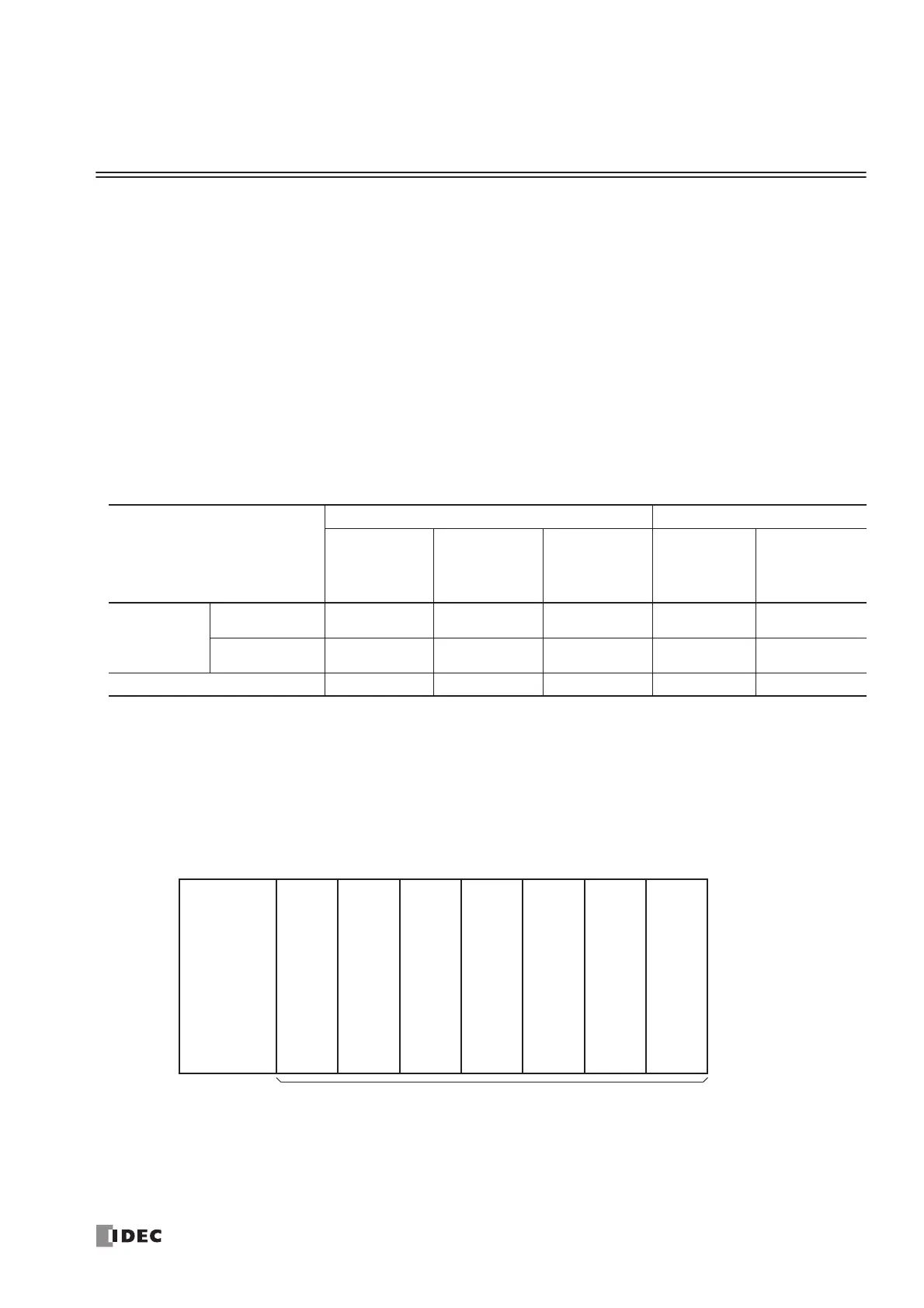
System Setup
The FC4A MicroSmart CPU modules can be used with a maximum of seven expansion I/O modules, which include digital
I/O modules and analog I/O modules.
System Setup Example
• Slot No.
Indicates the position where the expansion module is mounted. The slot number starts with 1 next to the CPU module up to
a maximum of 7.
FC4A MicroSmart
CPU Module
All-in-One Type Slim Type
FC4A-C10R2
FC4A-C10R2C
FC4A-C16R2
FC4A-C16R2C
FC4A-C24R2
FC4A-C24R2C
FC4A-D20K3
FC4A-D20S3
FC4A-D20RK1
FC4A-D20RS1
FC4A-D40K3
FC4A-D40S3
Applicable
CPU System
Program
Version
End Refresh — — Any Any Any
Ladder Refresh — — 204 or higher 204 or higher 203 or higher
Quantity of Analog I/O Modules — — 4 7 7
 Loading...


